


Mikroelektronika d.o.o.
Gleichstrommotor 17 Click-Platine
Gleichstrommotor 17 Click-Platine
SKU: MIKROE-4454
Verfügbarkeit für Abholungen konnte nicht geladen werden
Overview
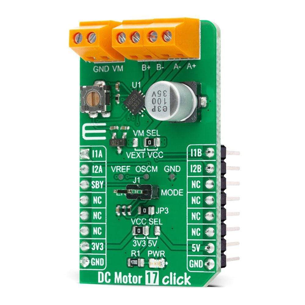
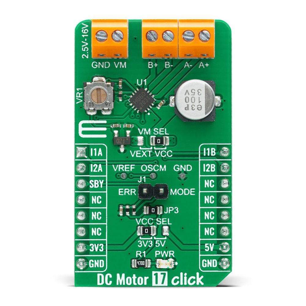
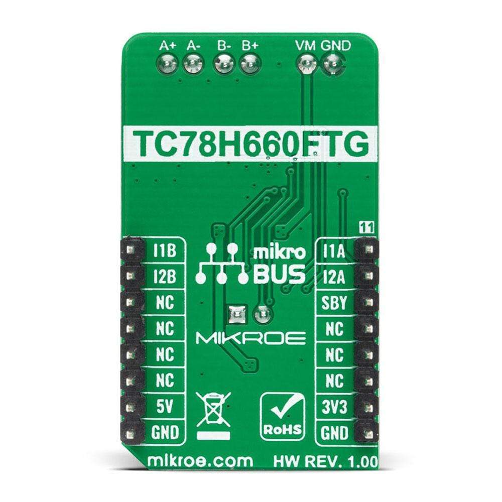
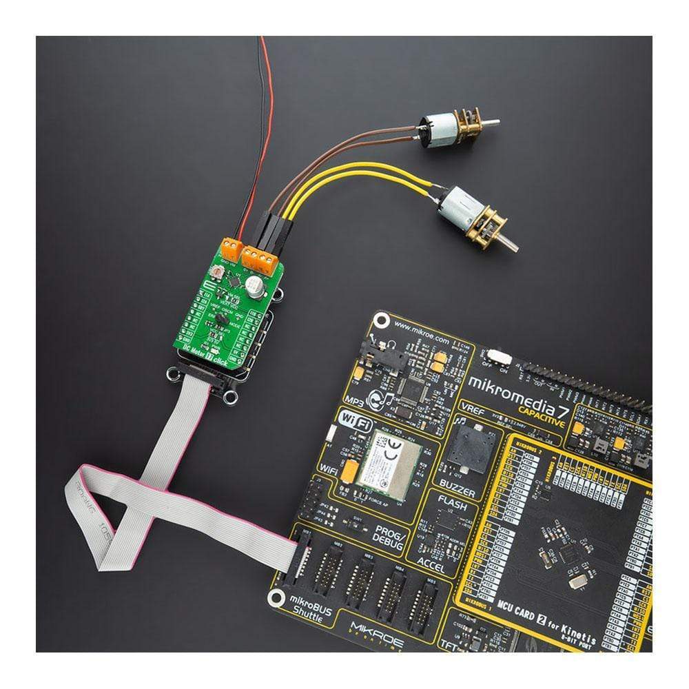
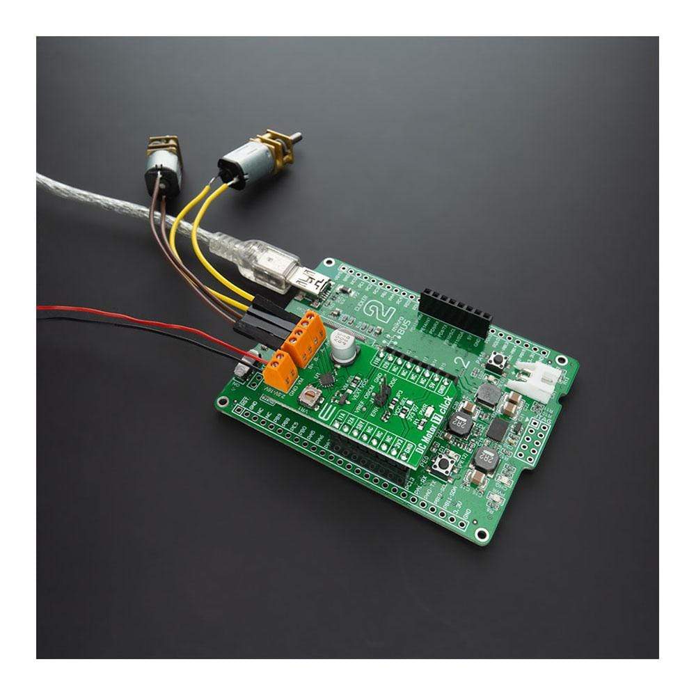
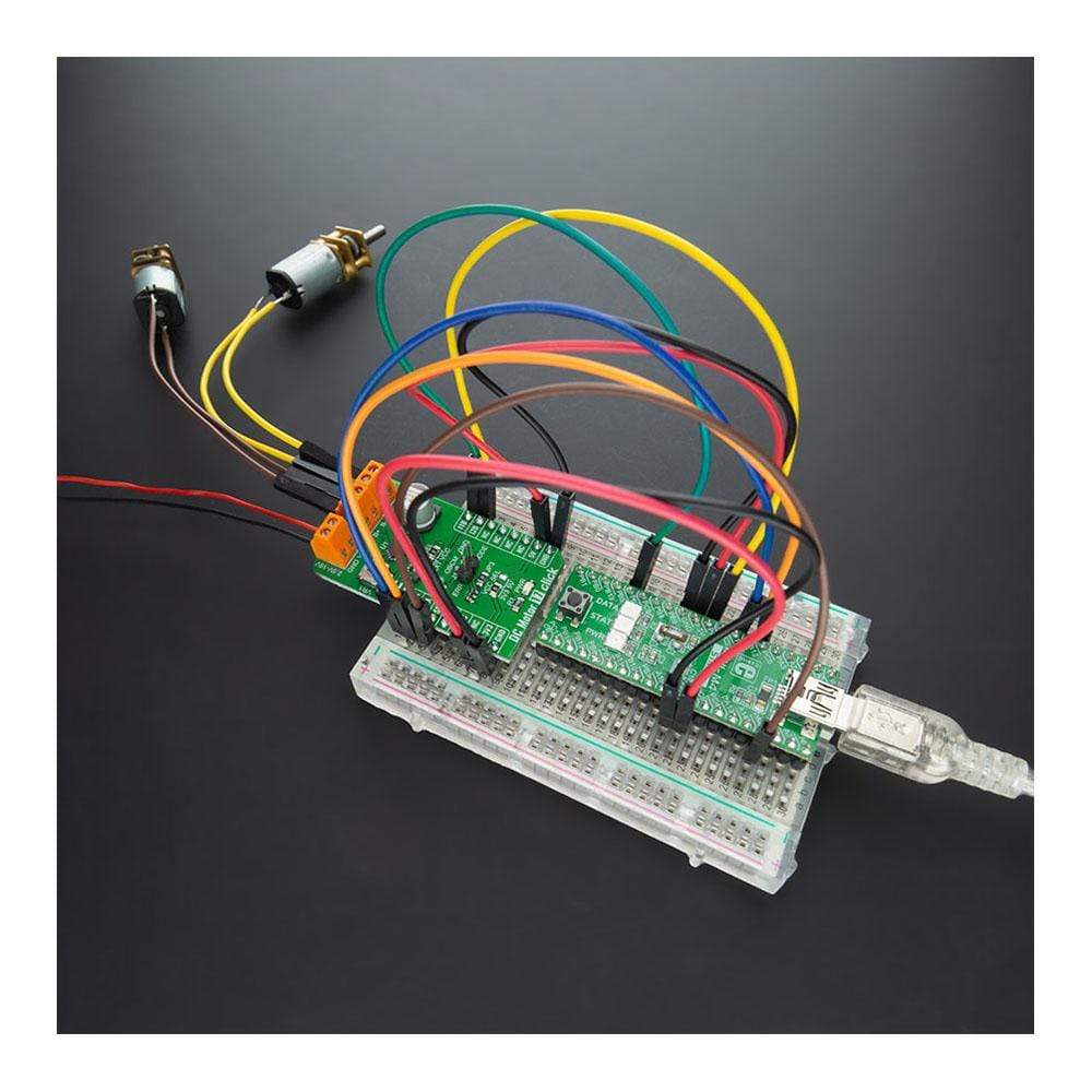
The DC Motor 17 Click™ Board is a compact add-on board that contains a brushed DC motor driver. This board features the TC78H660FTG, a dual H Bridge driver for one or two brushed motors that incorporate a DMOS output transistor with low on-resistance from Toshiba Semiconductor. This IC is a PWM controlled constant-current drive with supply voltages from 2.5V to 16V and 2A of output current. It features a sense-resistor less current control architecture and VCC regulator for the internal circuit. Also offers multi-error detect functions with error detection flag output function. This Click Board™ is suitable for driving DC motors, controlling the direction of the rotation, as well as brake and regulating the motor current.
The DC Motor 17 Click Board™ is supported by a mikroSDK compliant library, which includes functions that simplify software development. This Click Board™ comes as a fully tested product, ready to be used on a system equipped with the mikroBUS™ socket.
Downloads
Die DC Motor 17 Click™-Platine ist eine kompakte Zusatzplatine, die einen Treiber für einen bürstenbehafteten Gleichstrommotor enthält. Diese Platine verfügt über den TC78H660FTG, einen dualen H-Brückentreiber für einen oder zwei bürstenbehaftete Motoren, der einen DMOS-Ausgangstransistor mit niedrigem Einschaltwiderstand von Toshiba Semiconductor enthält. Dieser IC ist ein PWM-gesteuerter Konstantstromantrieb mit Versorgungsspannungen von 2,5 V bis 16 V und 2 A Ausgangsstrom. Er verfügt über eine widerstandslose Stromsteuerungsarchitektur und einen VCC-Regler für den internen Schaltkreis. Bietet außerdem Mehrfachfehlererkennungsfunktionen mit Fehlererkennungs-Flag-Ausgabefunktion. Diese Click Board™ eignet sich zum Antrieb von Gleichstrommotoren, zur Steuerung der Drehrichtung sowie zum Bremsen und Regeln des Motorstroms.
Das DC Motor 17 Click Board™ wird von einer mikroSDK-kompatiblen Bibliothek unterstützt, die Funktionen enthält, die die Softwareentwicklung vereinfachen. Dieses Click Board™ wird als vollständig getestetes Produkt geliefert und ist bereit für den Einsatz auf einem System, das mit der mikroBUS™-Buchse ausgestattet ist.
| General Information | |
|---|---|
Part Number (SKU) |
MIKROE-4454
|
Manufacturer |
|
| Physical and Mechanical | |
Weight |
0.02 kg
|
| Other | |
EAN |
8606027381300
|
Frequently Asked Questions
Have a Question?
Be the first to ask a question about this.