


Mikroelektronika d.o.o.
Binho Nova Klickbrett
Binho Nova Klickbrett
SKU: MIKROE-4439
Verfügbarkeit für Abholungen konnte nicht geladen werden


Key Features
Overview
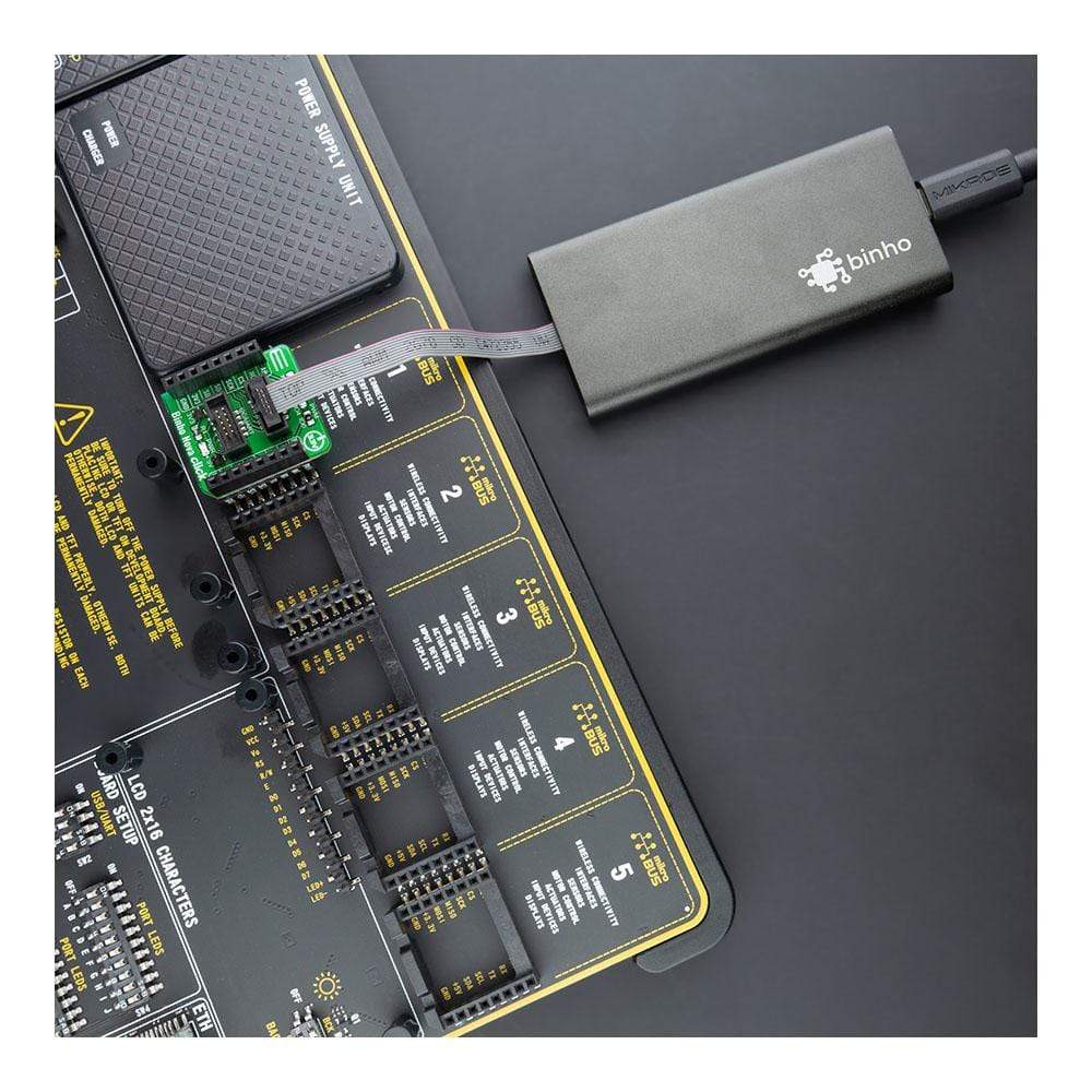
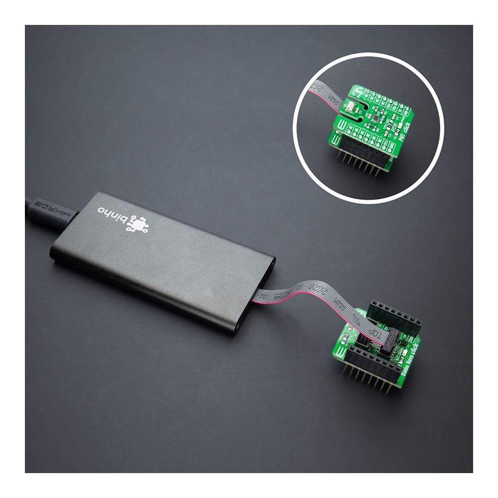
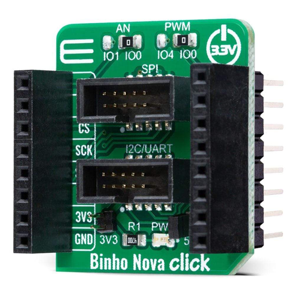
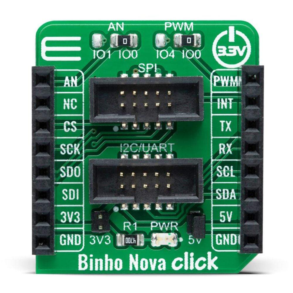
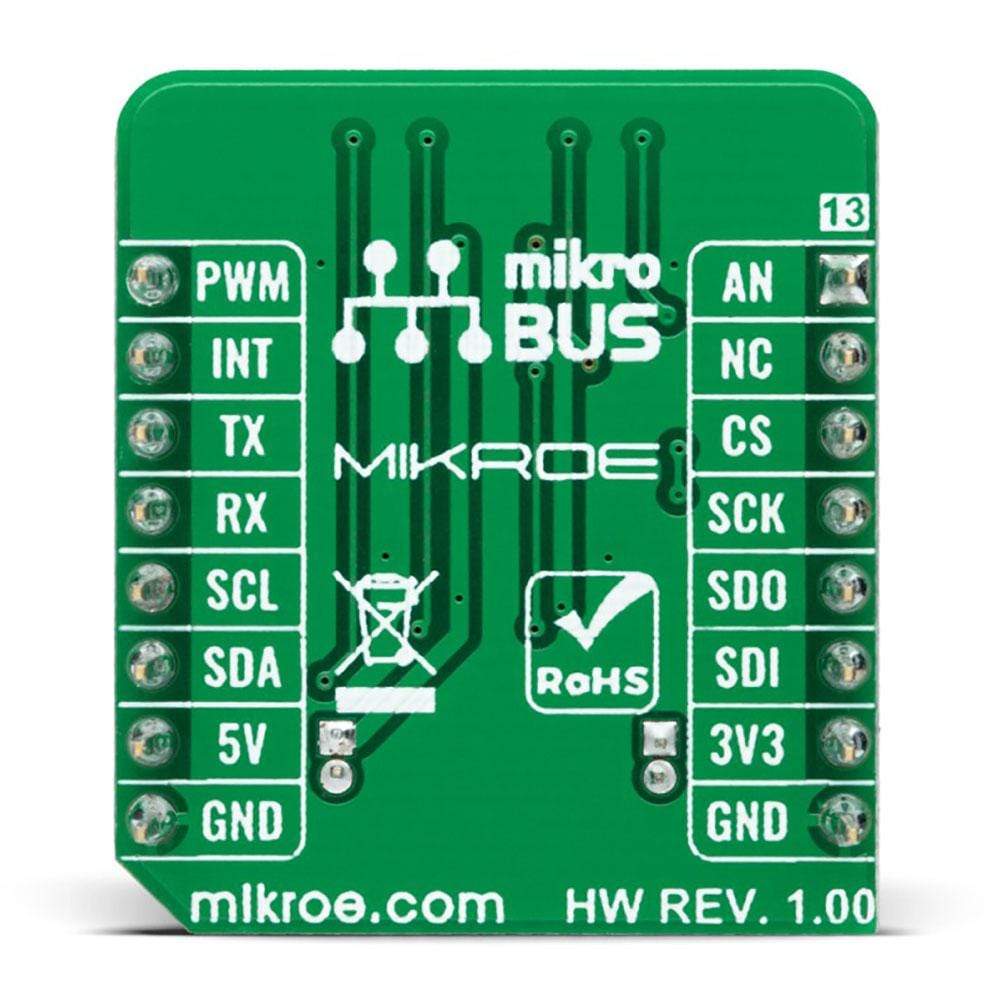
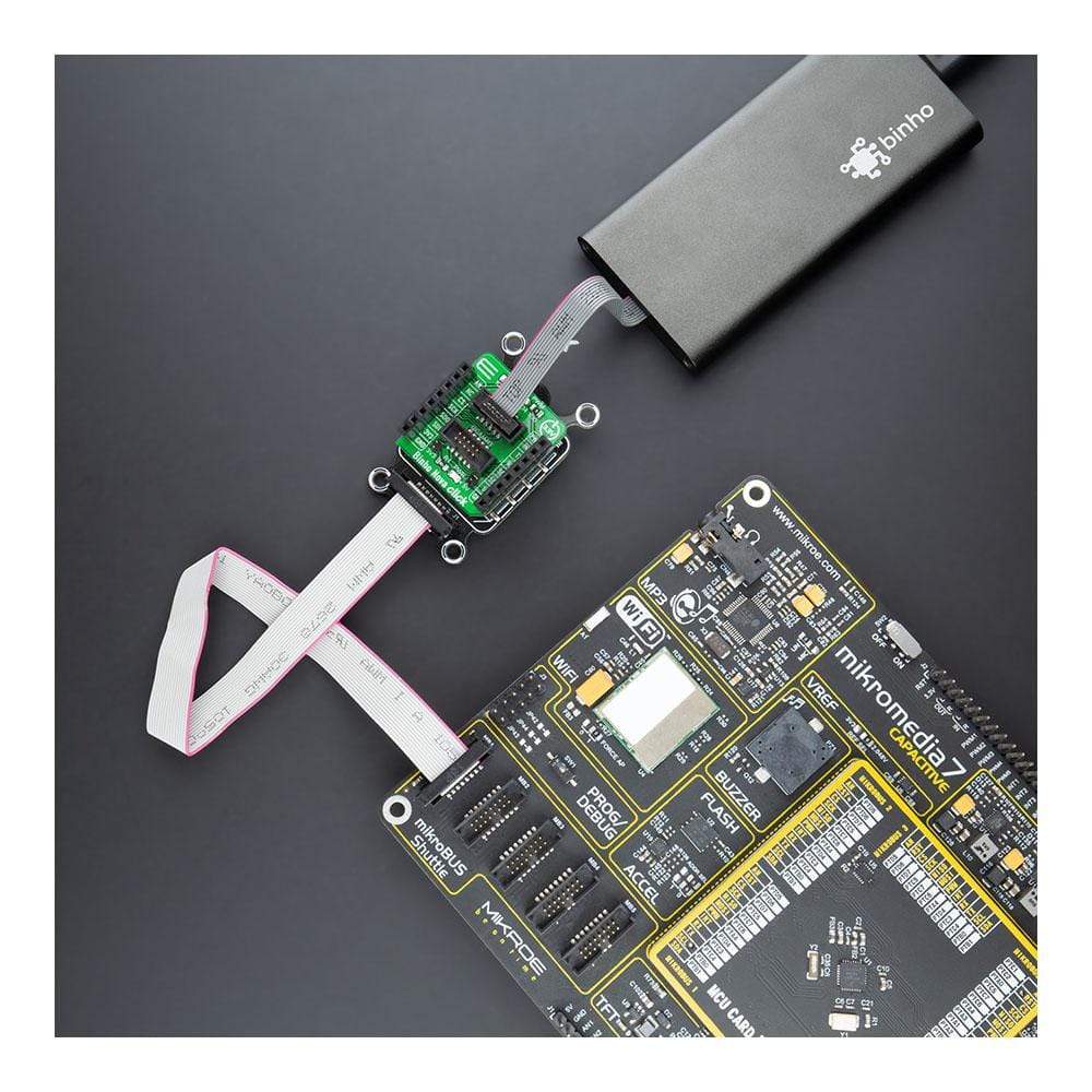
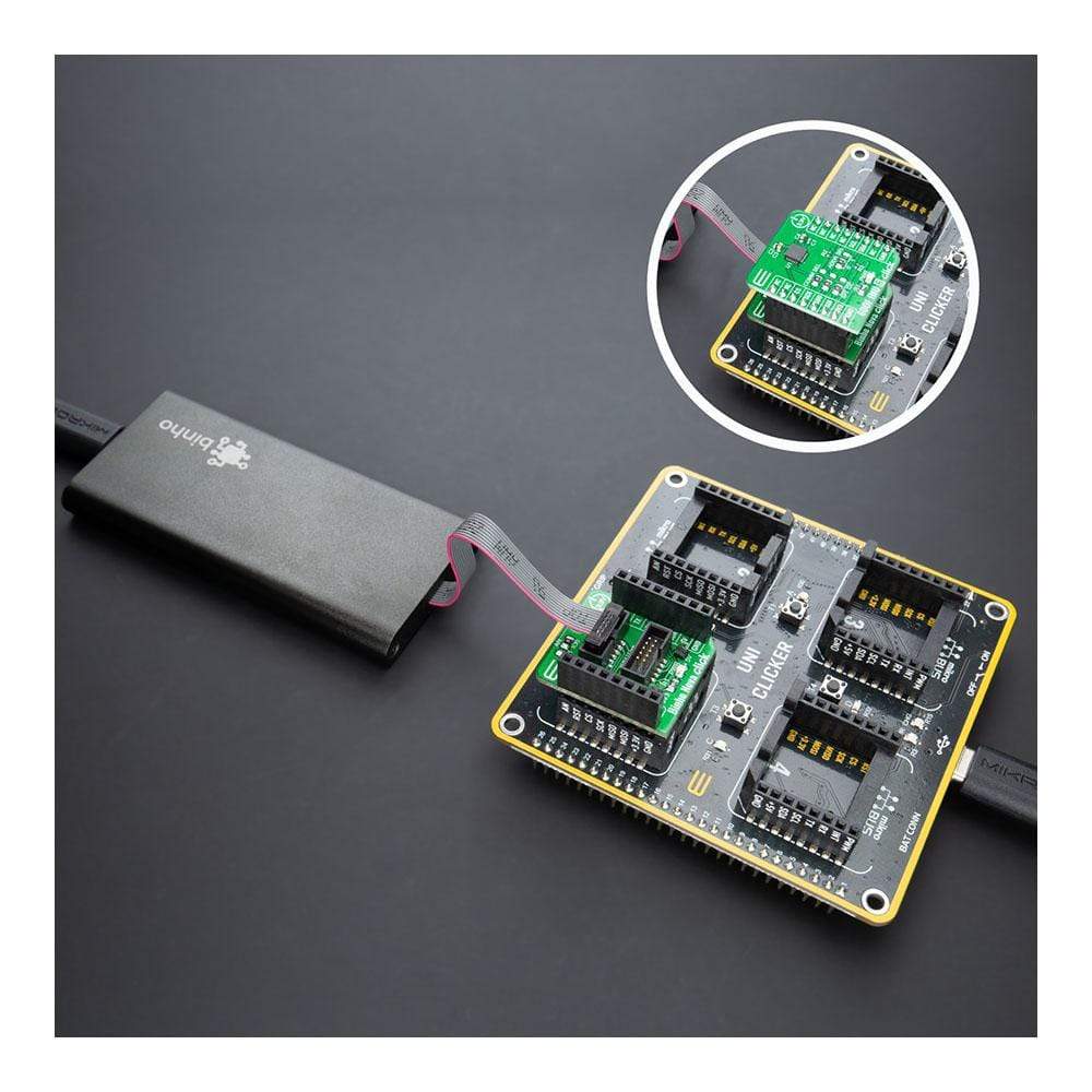
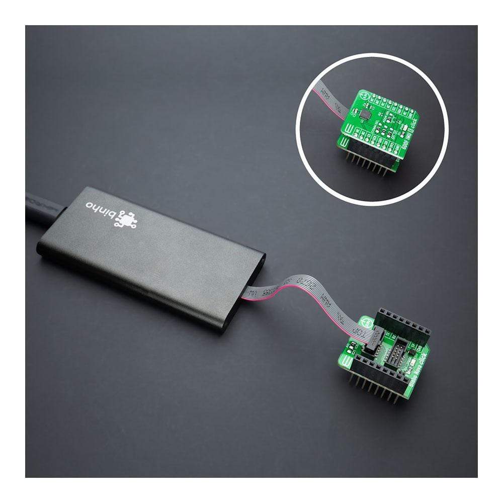
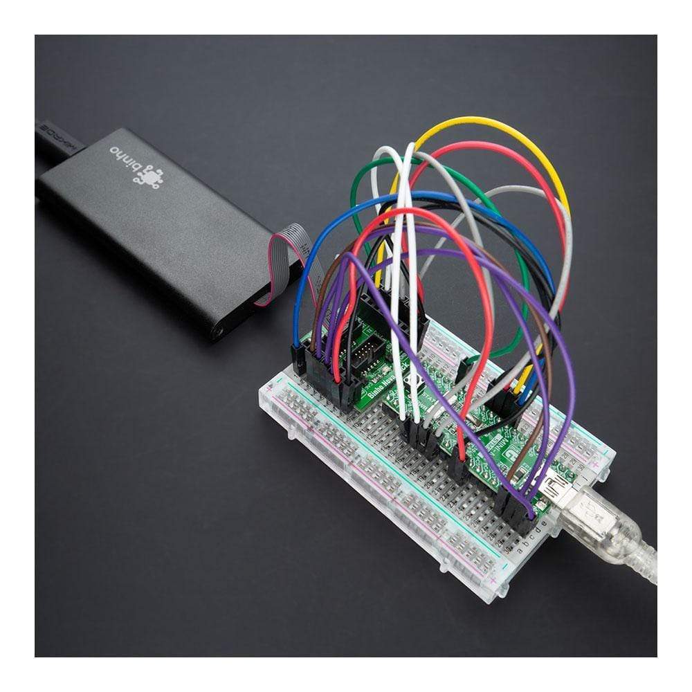
The Binho Nova Click Board™ is an adapter that can be used as a multi-protocol adapter. This board features two female 1.27mm 2x5 connectors suitable for connecting the Binho Nova Multi-Protocol USB Host Adapter, depending on the desired interface. This Click Board™ is designed for ultimate flexibility and allows the use of this adapter with different communication protocols, such as I2C, SPI, or UART. It features five signal pins, which can be used as Digital Input/Output, PWM Output, Digital Interrupt, or Analog Input/Output. Along with these connectors, it also features two power jumpers that can be used to supply the host from the Binho Nova. This Click Board™ is suitable for manual testing during firmware development, debugging, and automating hardware testing and validation.
NOTE: The Binho Nova Click Board™ comes with stacking headers that allow you to easily combine it with other Click boards™ by using just one mikroBUS™ socket.
Downloads
Das Binho Nova Click Board™ ist ein Adapter, der als Multiprotokolladapter verwendet werden kann. Diese Platine verfügt über zwei 1,27-mm-2x5-Buchsen, die je nach gewünschter Schnittstelle zum Anschluss des Binho Nova Multiprotokoll-USB-Hostadapters geeignet sind. Dieses Click Board™ ist auf höchste Flexibilität ausgelegt und ermöglicht die Verwendung dieses Adapters mit verschiedenen Kommunikationsprotokollen wie I2C, SPI oder UART. Es verfügt über fünf Signalstifte, die als digitaler Eingang/Ausgang, PWM-Ausgang, digitaler Interrupt oder analoger Eingang/Ausgang verwendet werden können. Neben diesen Steckverbindern verfügt es auch über zwei Strombrücken, mit denen der Host vom Binho Nova aus versorgt werden kann. Dieses Click Board™ eignet sich für manuelle Tests während der Firmware-Entwicklung, zum Debuggen und zum Automatisieren von Hardwaretests und -validierungen.
HINWEIS: Das Binho Nova Click Board™ wird mit stapelbaren Headern geliefert, die Ihnen eine einfache Kombination mit anderen Click Boards™ mithilfe nur einer MikroBUS™-Buchse ermöglichen.
| General Information | |
|---|---|
Part Number (SKU) |
MIKROE-4439
|
Manufacturer |
|
| Physical and Mechanical | |
Weight |
0.018 kg
|
| Other | |
EAN |
8606027381263
|
Frequently Asked Questions
Have a Question?
Be the first to ask a question about this.