


Mikroelektronika d.o.o.
I2C Extend 2 Click-Platine
I2C Extend 2 Click-Platine
SKU: MIKROE-4419
Verfügbarkeit für Abholungen konnte nicht geladen werden
Overview
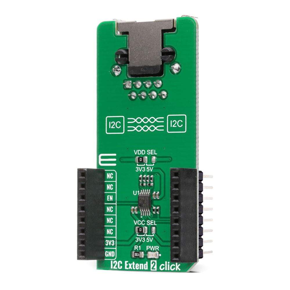
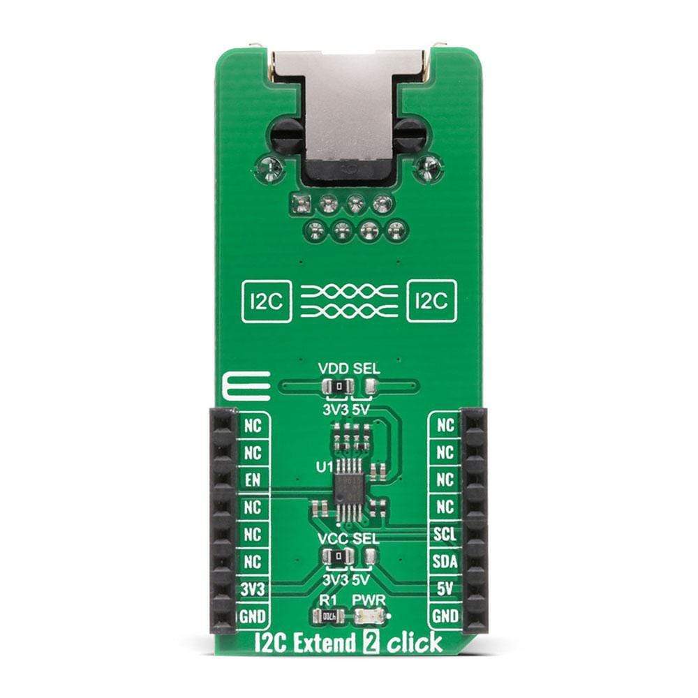
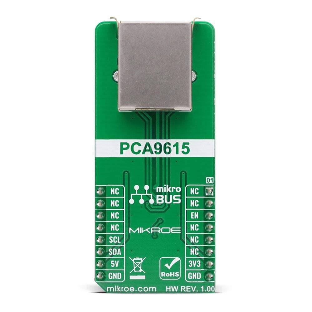
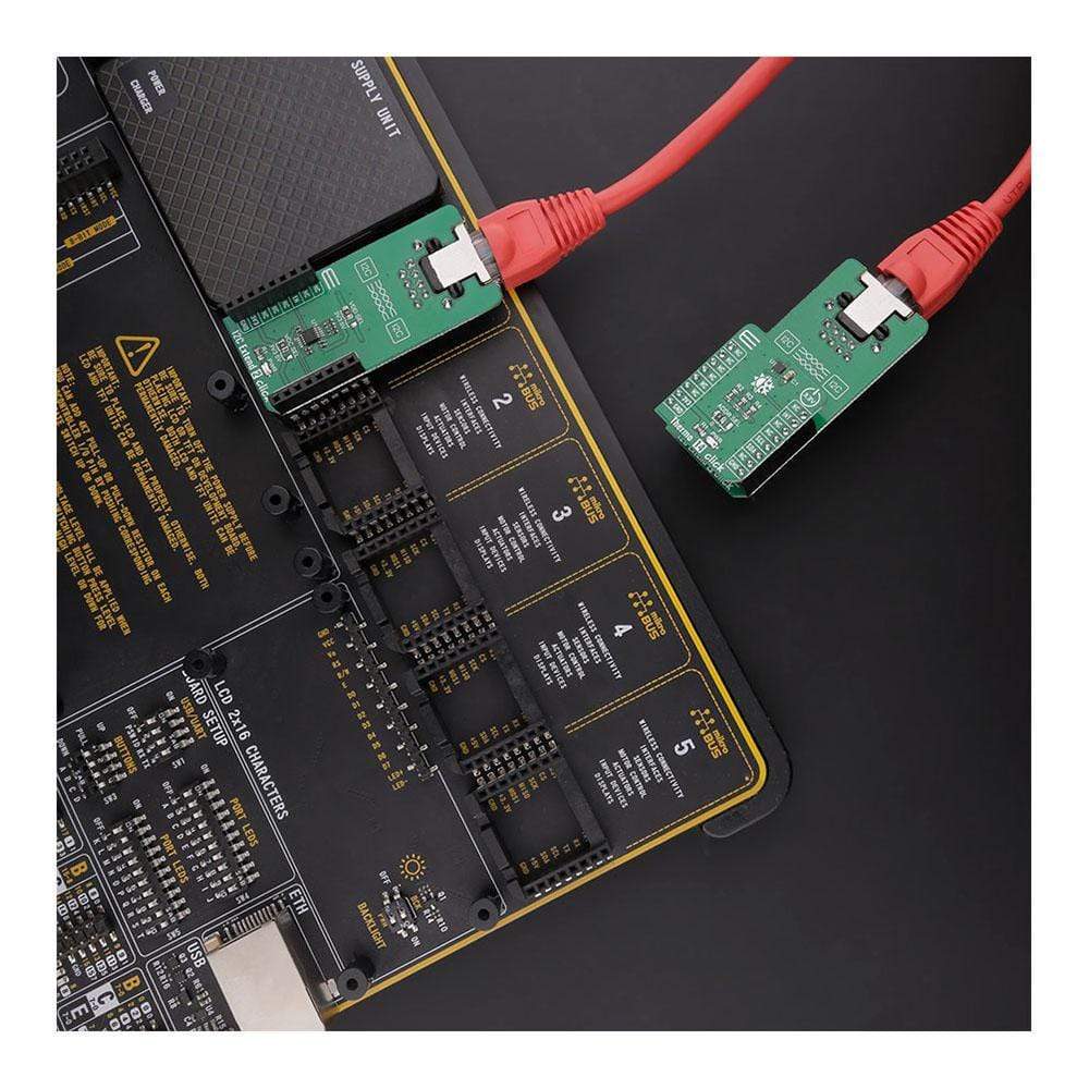
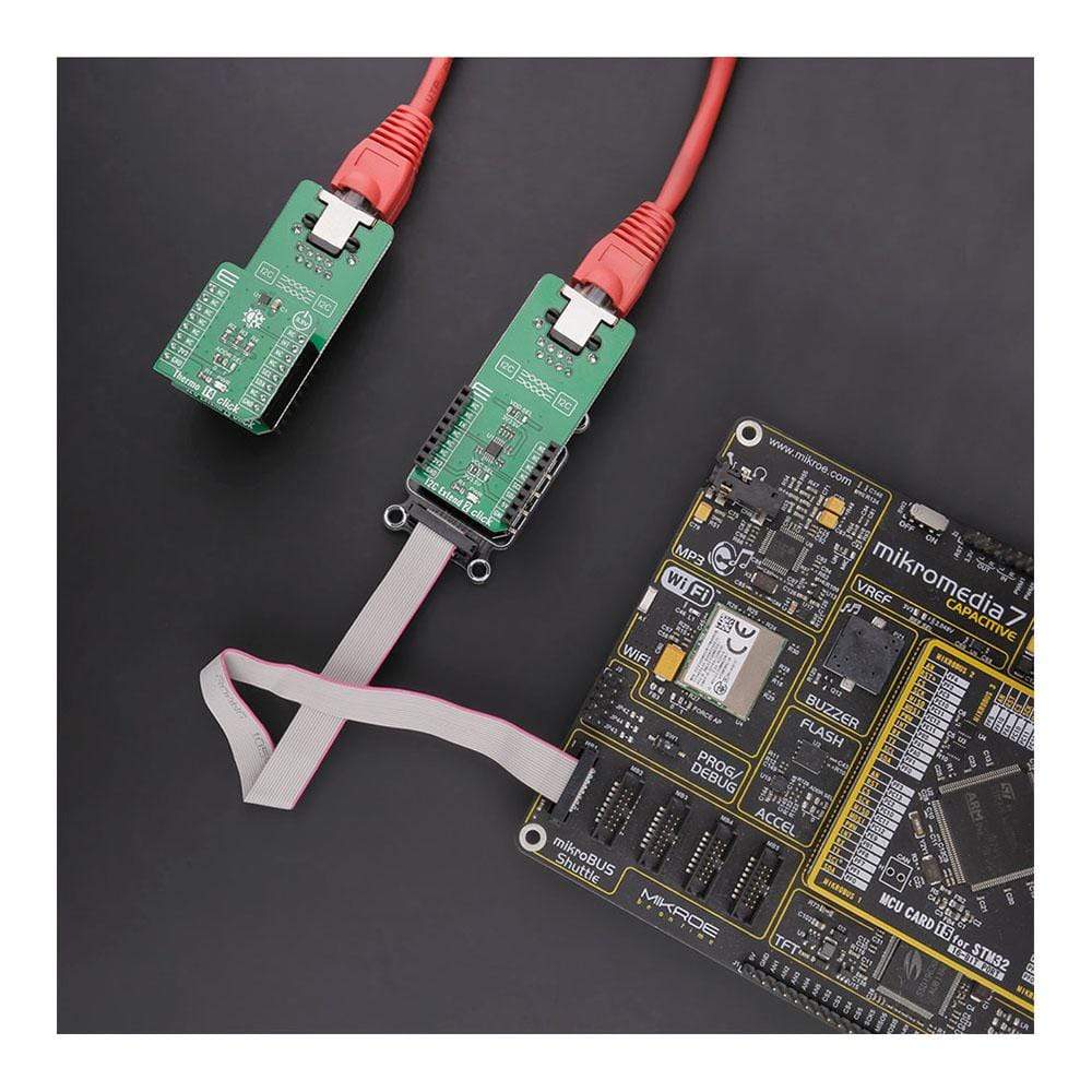
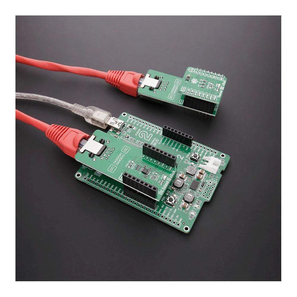
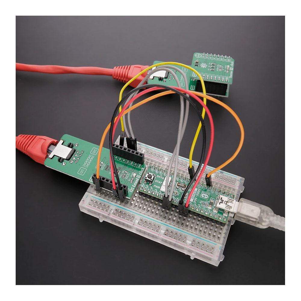
The I2C Extend 2 Click Board™ is a compact add-on board suitable for I2C communication bus extension. This board features the PCA9615, a 2-channel multipoint differential I2C bus buffer with hot-swap logic from NXP Semiconductors. The PCA9615 converts the two default I2C signals into four differential signals, two for SCL and two for SDA. The differential signals allow the I2C signals to reach distances of up to 3m while maintaining their signal integrity sent over an Ethernet cable through the onboard RJ-45 connector. This Click Board™ is suitable for various applications that require extending the I2C bus over a long distance, such as commercial lighting and industrial control, control of power supplies in a high noise environment, and more.
The I2C Extend 2 Click Board™ is supported by a mikroSDK compliant library, which includes functions that simplify software development. This Click Board™ comes as a fully tested product, ready to be used on a system equipped with the mikroBUS™ socket.
Downloads
Der I2C Extend 2 Click Board™ ist eine kompakte Zusatzplatine, die für die Erweiterung des I2C-Kommunikationsbusses geeignet ist. Diese Platine verfügt über den PCA9615, einen 2-Kanal-Mehrpunkt-Differential-I2C-Buspuffer mit Hot-Swap-Logik von NXP Semiconductors. Der PCA9615 wandelt die beiden Standard-I2C-Signale in vier Differenzsignale um, zwei für SCL und zwei für SDA. Die Differenzsignale ermöglichen es den I2C-Signalen, Entfernungen von bis zu 3 m zu erreichen, während ihre Signalintegrität über ein Ethernet-Kabel über den integrierten RJ-45-Anschluss erhalten bleibt. Dieses Click Board™ ist für verschiedene Anwendungen geeignet, bei denen der I2C-Bus über eine große Entfernung erweitert werden muss, wie z. B. kommerzielle Beleuchtung und industrielle Steuerung, Steuerung von Stromversorgungen in einer Umgebung mit hohem Rauschen und mehr.
Das I2C Extend 2 Click Board™ wird von einer mikroSDK-kompatiblen Bibliothek unterstützt, die Funktionen enthält, die die Softwareentwicklung vereinfachen. Dieses Click Board™ wird als vollständig getestetes Produkt geliefert und ist bereit für den Einsatz auf einem System, das mit der mikroBUS™-Buchse ausgestattet ist.
| General Information | |
|---|---|
Part Number (SKU) |
MIKROE-4419
|
Manufacturer |
|
| Physical and Mechanical | |
Weight |
0.023 kg
|
| Other | |
EAN |
8606027381218
|
Frequently Asked Questions
Have a Question?
Be the first to ask a question about this.