Bürstenloses 12-Click-Board
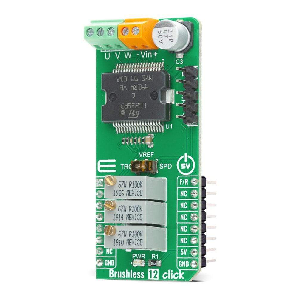
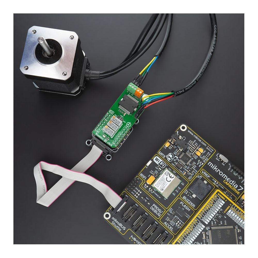
Das Brushless 12 Click Board™ ist eine kompakte Zusatzplatine, die BLDC-Motoren mit jedem MCU steuert. Diese Platine verfügt über den vollständig integrierten 3-Phasen-Motortreiber L6235 DMOS mit Überstromschutz von STMicroelectronics. Der L6235 kombiniert die isolierten DMOS-Leistungstransistoren des Chips mit CMOS- und bipolaren Schaltkreisen. Er verfügt über einen nichtdissipativen Überstromschutz an den High-Side-Leistungs-MOSFETs und eine thermische Abschaltung und umfasst alle Schaltkreise, die zum Antrieb eines 3-Phasen-bürstenlosen Gleichstrommotors erforderlich sind. Dieses Click Board™ ist die perfekte Lösung für kleine Haushaltsgeräte, Roboter, batteriebetriebene Systeme, kleine Kühllüfter und vieles mehr.
Das Brushless 12 Click wird von einer mikroSDK-kompatiblen Bibliothek unterstützt, die Funktionen enthält, die die Softwareentwicklung vereinfachen. Dieses Click Board™ ist ein gründlich getestetes Produkt und kann auf einem System verwendet werden, das mit der mikroBUS™-Buchse ausgestattet ist.
How Does The The Brushless 12 Click Board™ Work?
The Brushless 12 Click Board™ is based on the L6235, fully integrated motor driver specifically developed to drive a wide range of BLDC motors with Hall effect sensors from STMicroelectronics. The L6235 includes a 3-phase DMOS bridge, an OFF-TIME PWM current controller, and the decoding logic for single-ended Hall sensors that generate the required sequence for the power stage, and other added features for safe operation and flexibility. It also has a built-in Over Current Detection (OCD) that allows protection against short circuits between the outputs and between output and ground.
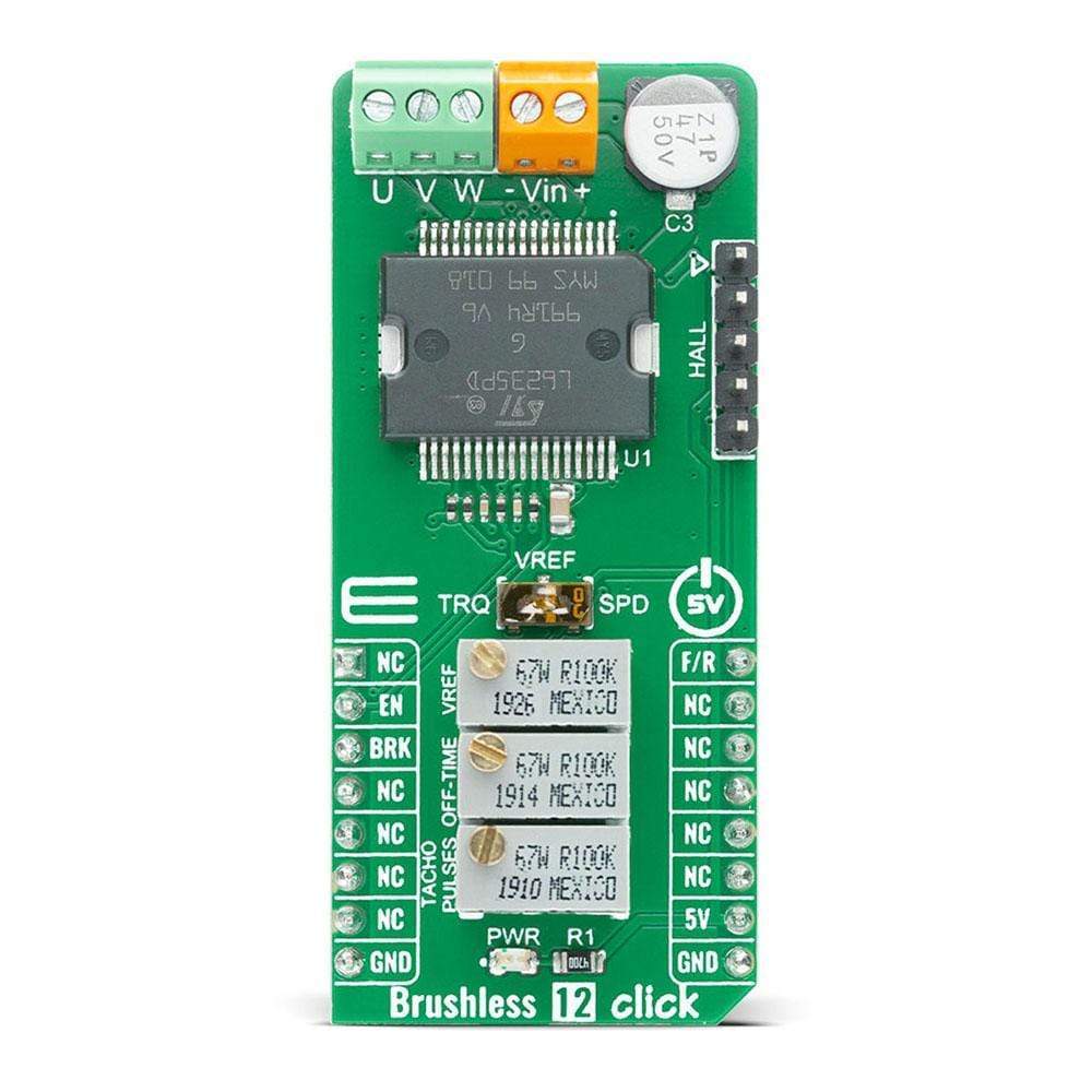
Integrated decoding logic of the L6235 provides the correct sequence on the three outputs labeled as U V W for motors with both 60° and 120° spaced Hall effect sensors signals. The sensor outputs are connected to the H1, H2, H3 inputs of the device through the header labeled as HALL. H1 input of the L6235 is internally connected to a monostable that provides a width pulse on the TACHO output. With a pull-up resistor on this output, the resulting waveform at the pin will be a square-wave whose frequency is proportional to the motor rotation speed, with an on-time set by the potentiometer VR1 labeled as TACHO. An additional potentiometer on the Brushless 12 Click Board™ VR2, labeled as OFF-TIME, can be used for a PWM current regulation capacity.
VR1 potentiometer defines the on-time integrated and compared to a voltage proportional to the desired speed by the Op-Amp LM358 also from STMicroelectronics. The output of the Op-Amp represents the speed error signal. Providing this signal to the VREF input of the L6235, which sets the current in the motor windings, the speed error will act on the motor modifying its torque to maintain the speed at a constant value. This feature of the L6235 can be selected by the switch labeled as VREF that allows the selection between Torque or Speed Mode.
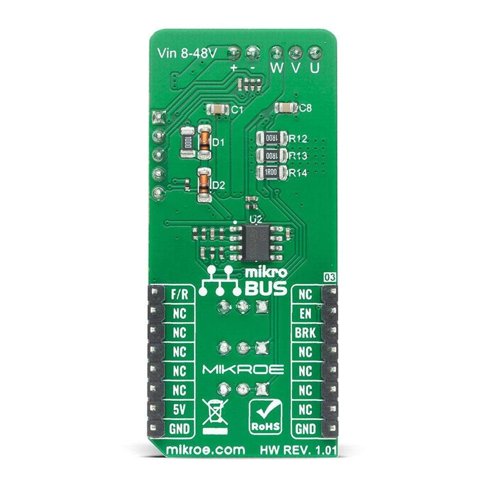
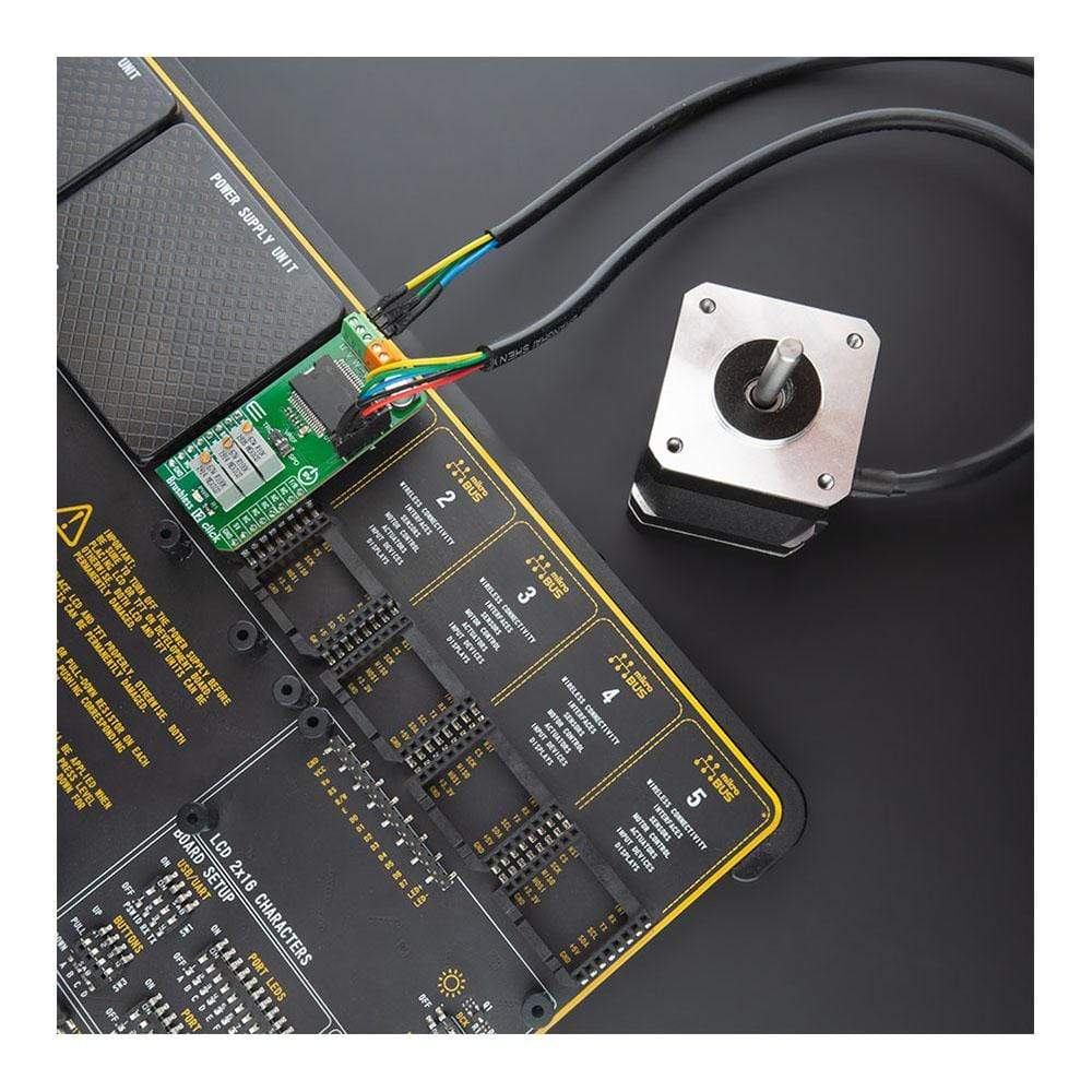
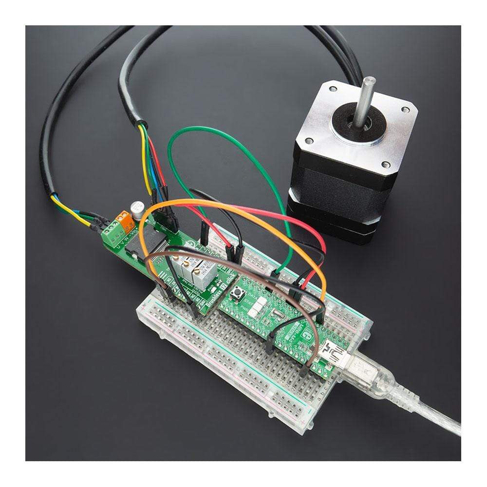
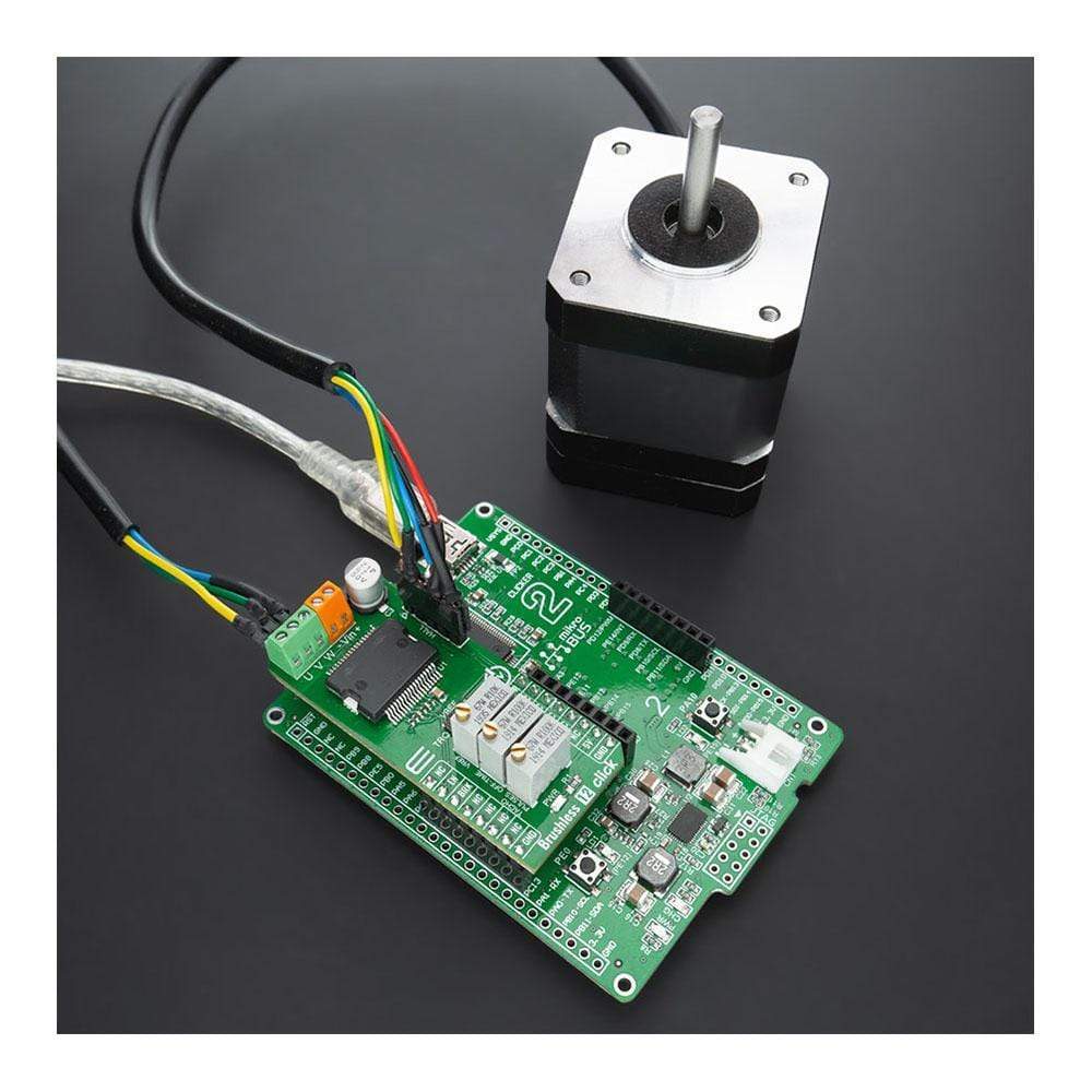
The Brushless 12 Click Board™ communicates with MCU using several GPIO pins. The RST pin of the mikroBUS™ socket labeled as EN represents the Enable function and serves as Chip Enable that turns OFF all power MOSFETs of the L6235. CS pin labeled as BRK switches ON all high-side power MOSFETs and allows the user to use the brake function. And the last GPIO pin routed to the PWM pin of the mikroBUS™ socket labeled as F/R selects the direction of the motor rotation. It also possesses two connectors, where one of them represents an external power supply labeled as VIN in the range from 8 to 48V maximum, and the next one labeled with U V W is a terminal on which the BLDC motor needs to be connected.
The Brushless 12 Click Board™ is designed to be operated only with a 5V logic voltage level. A proper logic voltage level conversion should be performed before the Click board™ is used with MCUs with different logic levels. However, the Click board™ comes equipped with a library that contains easy to use functions and an example code which can be used, as a reference, for further development.
SPECIFICATIONS
Type | Brushless |
Applications | Can be used for small home appliances, robotics, battery-powered systems, small cooling fans, and many more. |
On-board modules | The Brushless 12 Click Board™ is based on the L6235, fully integrated motor driver specifically developed to drive a wide range of BLDC motors with Hall effect sensors from STMicroelectronics. |
Key Features | Overcurrent detection and protection, undervoltage lockout, PWM current controller, brake function, tachometer output for speed loop, thermal shutdown, and more. |
Interface | PWM,GPIO |
Compatibility | mikroBUS |
Click board size | L (57.15 x 25.4 mm) |
Input Voltage | 5V,External |
PINOUT DIAGRAM
This table shows how the pinout on Brushless 12 Click corresponds to the pinout on the mikroBUS™ socket (the latter shown in the two middle columns).
Notes | Pin | Pin | Notes | ||||
---|---|---|---|---|---|---|---|
NC | 1 | AN | PWM | 16 | F/R | Forward/Reverse | |
Enable | EN | 2 | RST | INT | 15 | NC | |
Brake | BRK | 3 | CS | RX | 14 | NC | |
NC | 4 | SCK | TX | 13 | NC | ||
NC | 5 | MISO | SCL | 12 | NC | ||
NC | 6 | MOSI | SDA | 11 | NC | ||
NC | 7 | 3.3V | 5V | 10 | 5V | Power Supply | |
Ground | GND | 8 | GND | GND | 9 | GND | Ground |
ONBOARD SETTINGS AND INDICATORS
Label | Name | Default | Description |
---|---|---|---|
LD1 | PWR | - | Power LED Indicator |
J1 | HALL | Populated | External Hall Effect Sensor Pins |
SW1 | VREF | Right | Torque or Speed Mode Selection |
TR1 | VR1 | - | Tacho Pulses Adjustment Potentiometer |
TR2 | VR2 | - | OFF-Time Adjustment Potentiometer |
TR3 | VR3 | - | VREF Adjustment Potentiometer |
BRUSHLESS 12 CLICK ELECTRICAL SPECIFICATIONS
Description | Min | Typ | Max | Unit |
---|---|---|---|---|
Supply Voltage VIN | 7 | - | 52 | V |
Maximum Output Current | - | - | 2.8 | A |
Switching frequency | - | - | 100 | kHz |
Operating Temperature Range | -40 | - | +150 | °C |
Software Support
We provide a library for the Brushless 12 Click Board™ on our LibStock page, as well as a demo application (example), developed using MikroElektronika compilers. The demo can run on all the main MikroElektronika development boards.
Library Description
The library contains a basic functions for using the Brushless 12 Click Board™.
Key Functions
void brushless12_power_mode ( uint8_t mode )
- Sets motor power modevoid brushless12_work_mode ( uint8_t state )
- Sets motor work modevoid brushless12_direction ( uint8_t dir )
- Sets motor direction
Example Description
The application is composed of three sections :
- System Initialization - Initializes all necessary GPIO pins
- Application Initialization - Initializes driver inti and enable motor
- Application Task - Every second toggles direction with the break.
void application_task ( ) { brushless12_direction ( BRUSHLESS12_DIR_CCW ); brushless12_work_mode ( BRUSHLESS12_START ); Delay_ms( 1000 ); brushless12_work_mode ( BRUSHLESS12_BREAK ); Delay_ms( 1000 ); brushless12_direction ( BRUSHLESS12_DIR_CW ); brushless12_work_mode ( BRUSHLESS12_START ); Delay_ms( 1000 ); brushless12_work_mode ( BRUSHLESS12_BREAK ); Delay_ms( 1000 ); } The full application code, and ready to use projects can be found on our LibStock page.
Other mikroE Libraries used in the example:
- UART Library (LOG)
Additional Notes and Information
Depending on the development board you are using, you may need a USB UART click, USB UART 2 click or RS232 click to connect to your PC, for development systems with no UART to USB interface available on the board. The terminal available in all MikroElektronika compilers, or any other terminal application of your choice, can be used to read the message.
MIKROSDK
The Brushless 12 Click Board™ is supported with mikroSDK - MikroElektronika Software Development Kit. To ensure proper operation of mikroSDK compliant Click board™ demo applications, mikroSDK should be downloaded from the LibStock and installed for the compiler you are using.
Bürstenloses 12-Click-Board
Frequently Asked Questions
Have a Question?
Be the first to ask a question about this.