


Mikroelektronika d.o.o.
CXPI Click-Platine
CXPI Click-Platine
SKU: MIKROE-4336
Verfügbarkeit für Abholungen konnte nicht geladen werden


Overview
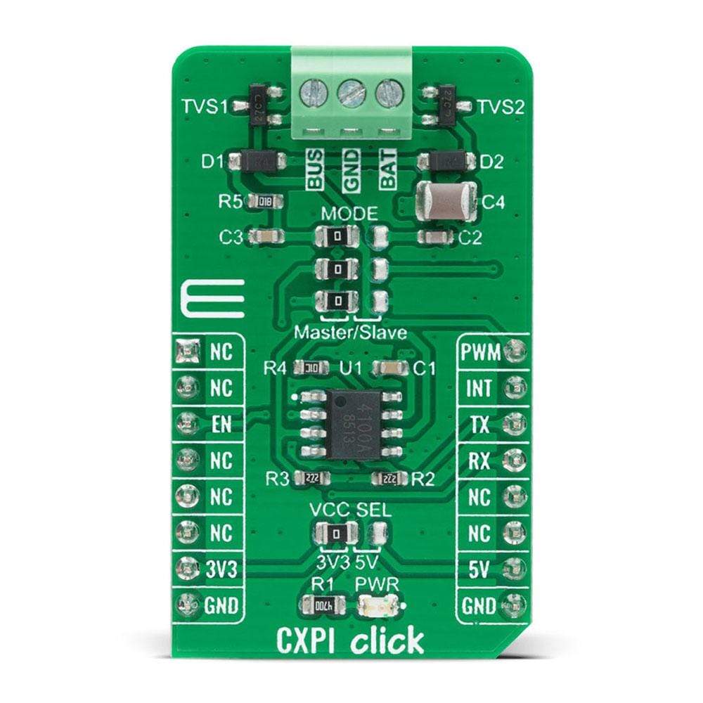
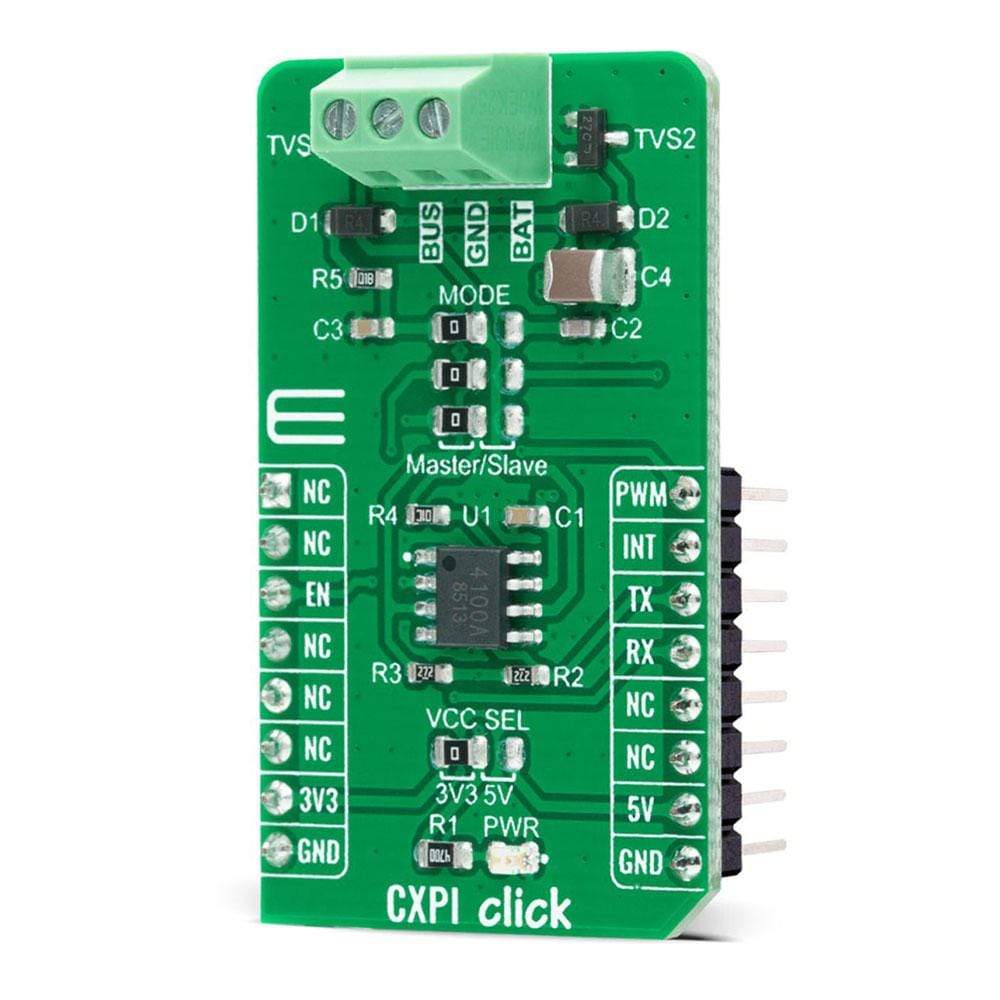
The CXPI Click Board™ is a compact add-on board that contains a transceiver that supports the next-generation automotive communication protocol. This board features the BD41000AFJ-C, a transceiver for the CXPI (Clock Extension Peripheral Interface) communication from Rohm Semiconductor. It operates from 7V to 18V external power supply, features easy switching between Master or Slave Mode, arbitration function that stops the data output upon detection of BUS data collision, and fail-safe functions that suspend the output data upon detection of under-voltage or temperature abnormality. This Click Board™ is suitable for use in body control applications, including steering switch, AC, and instrument panel systems.
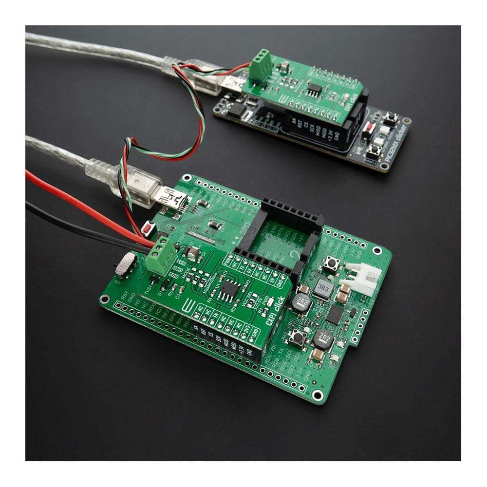
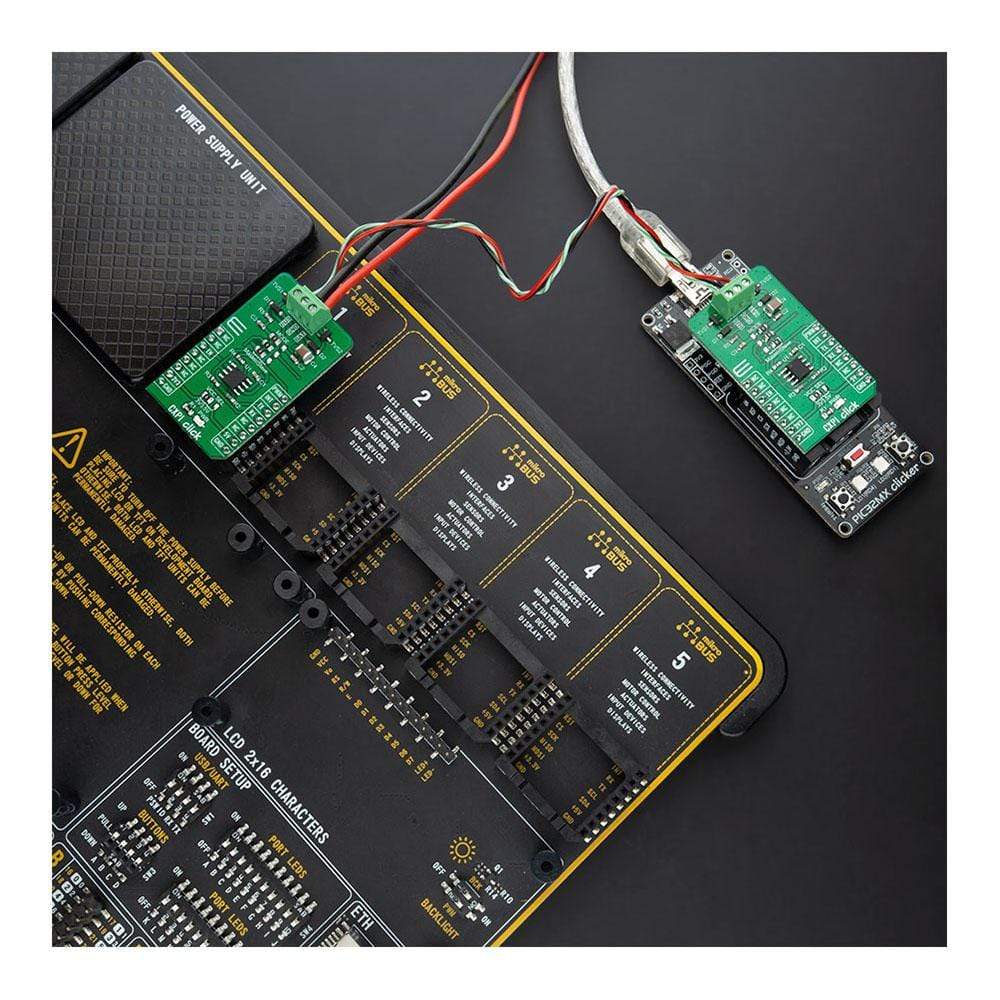
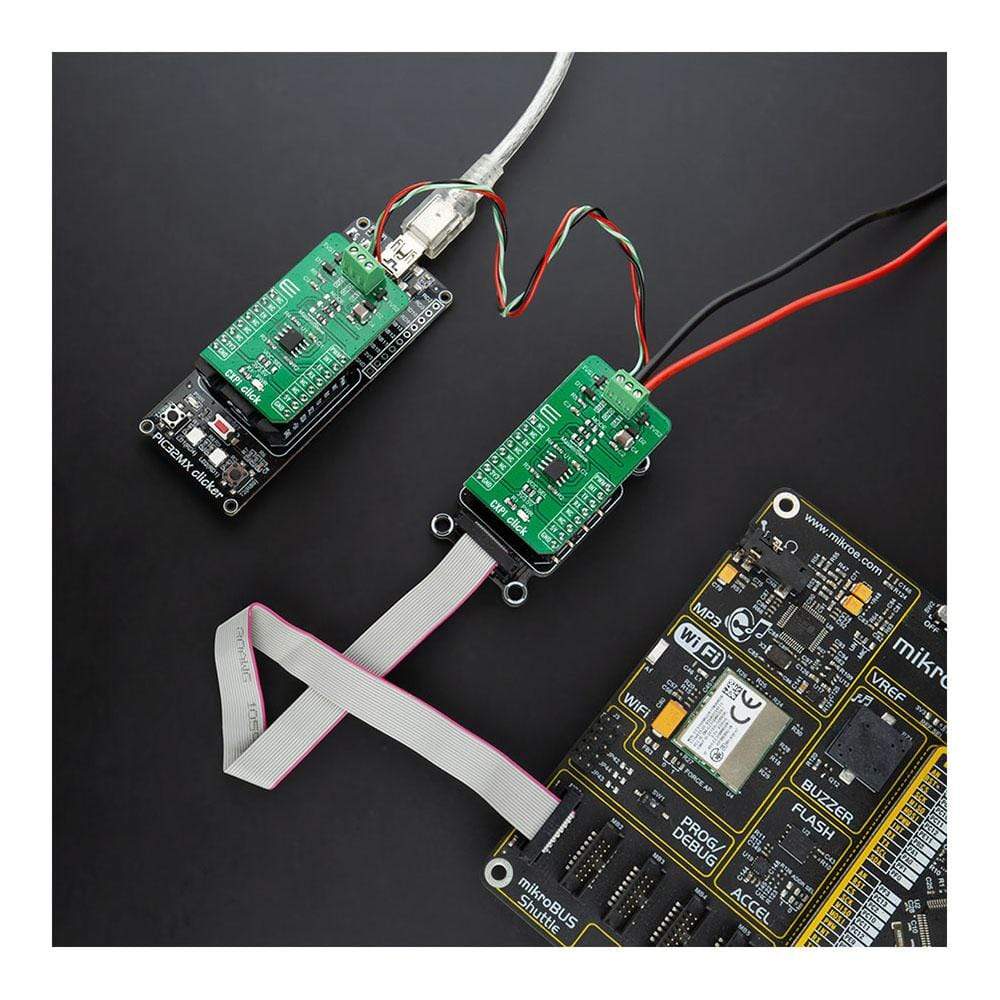
The CXPI Click Board™ is supported by a mikroSDK compliant library, which includes functions that simplify software development. This Click Board™ comes as a fully tested product, ready to be used on a system equipped with the mikroBUS™ socket.
Downloads
Der CXPI Click Board™ ist eine kompakte Zusatzplatine, die einen Transceiver enthält, der das Automobil-Kommunikationsprotokoll der nächsten Generation unterstützt. Diese Platine verfügt über den BD41000AFJ-C, einen Transceiver für die CXPI-Kommunikation (Clock Extension Peripheral Interface) von Rohm Semiconductor. Er arbeitet mit einer externen Stromversorgung von 7 V bis 18 V, bietet einfaches Umschalten zwischen Master- oder Slave-Modus, eine Arbitrierungsfunktion, die die Datenausgabe bei Erkennung einer BUS-Datenkollision stoppt, und ausfallsichere Funktionen, die die Ausgabedaten bei Erkennung einer Unterspannung oder einer Temperaturanomalie aussetzen. Dieses Click Board™ ist für den Einsatz in Karosseriesteuerungsanwendungen geeignet, einschließlich Lenkschalter, Klimaanlage und Instrumententafelsystemen.
Das CXPI Click Board™ wird von einer mikroSDK-kompatiblen Bibliothek unterstützt, die Funktionen enthält, die die Softwareentwicklung vereinfachen. Dieses Click Board™ wird als vollständig getestetes Produkt geliefert und ist bereit für den Einsatz auf einem System, das mit der mikroBUS™-Buchse ausgestattet ist.
| General Information | |
|---|---|
Part Number (SKU) |
MIKROE-4336
|
Manufacturer |
|
| Physical and Mechanical | |
Weight |
0.019 kg
|
| Other | |
EAN |
8606027381034
|
Frequently Asked Questions
Have a Question?
Be the first to ask a question about this.