


Mikroelektronika d.o.o.
NFC 2 Click-Platine
NFC 2 Click-Platine
SKU: MIKROE-4309
Verfügbarkeit für Abholungen konnte nicht geladen werden


Overview
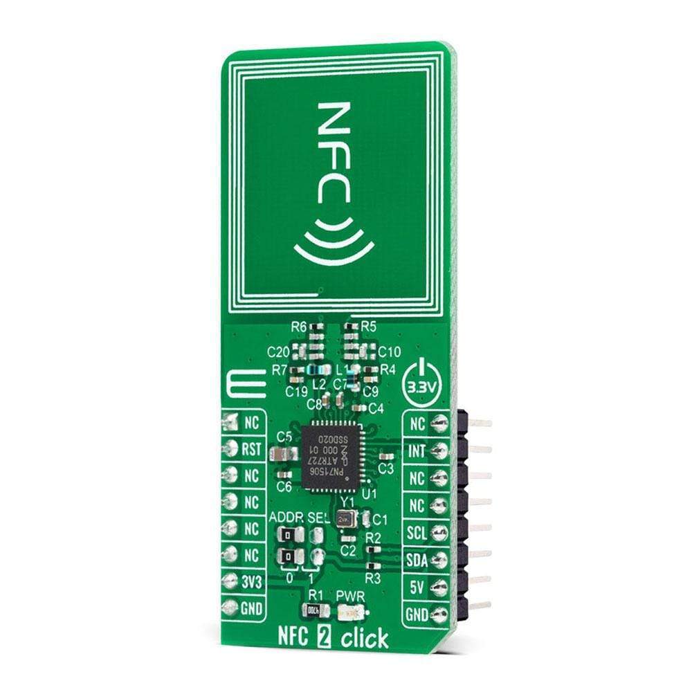
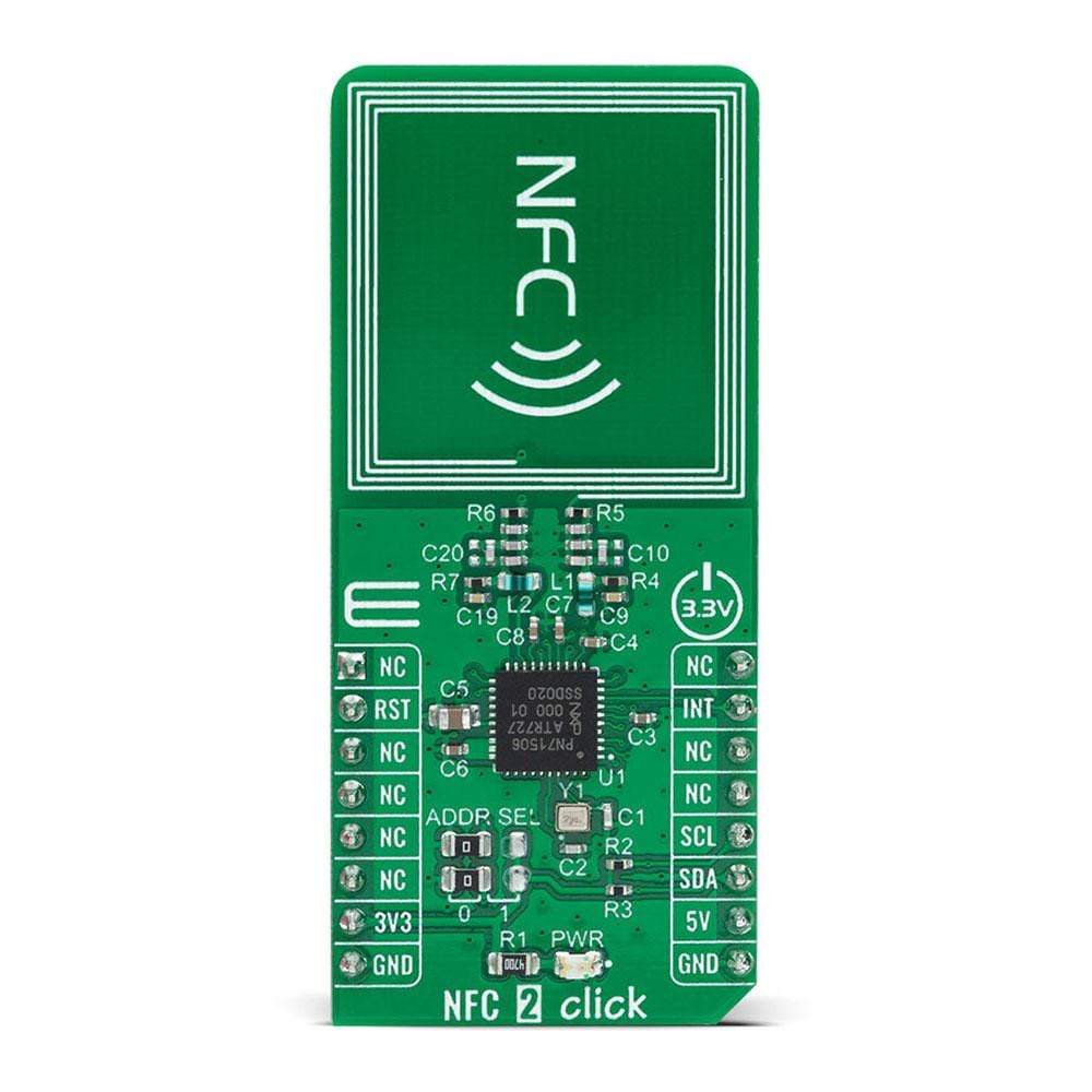
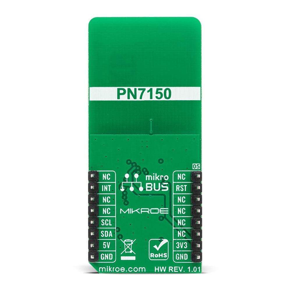
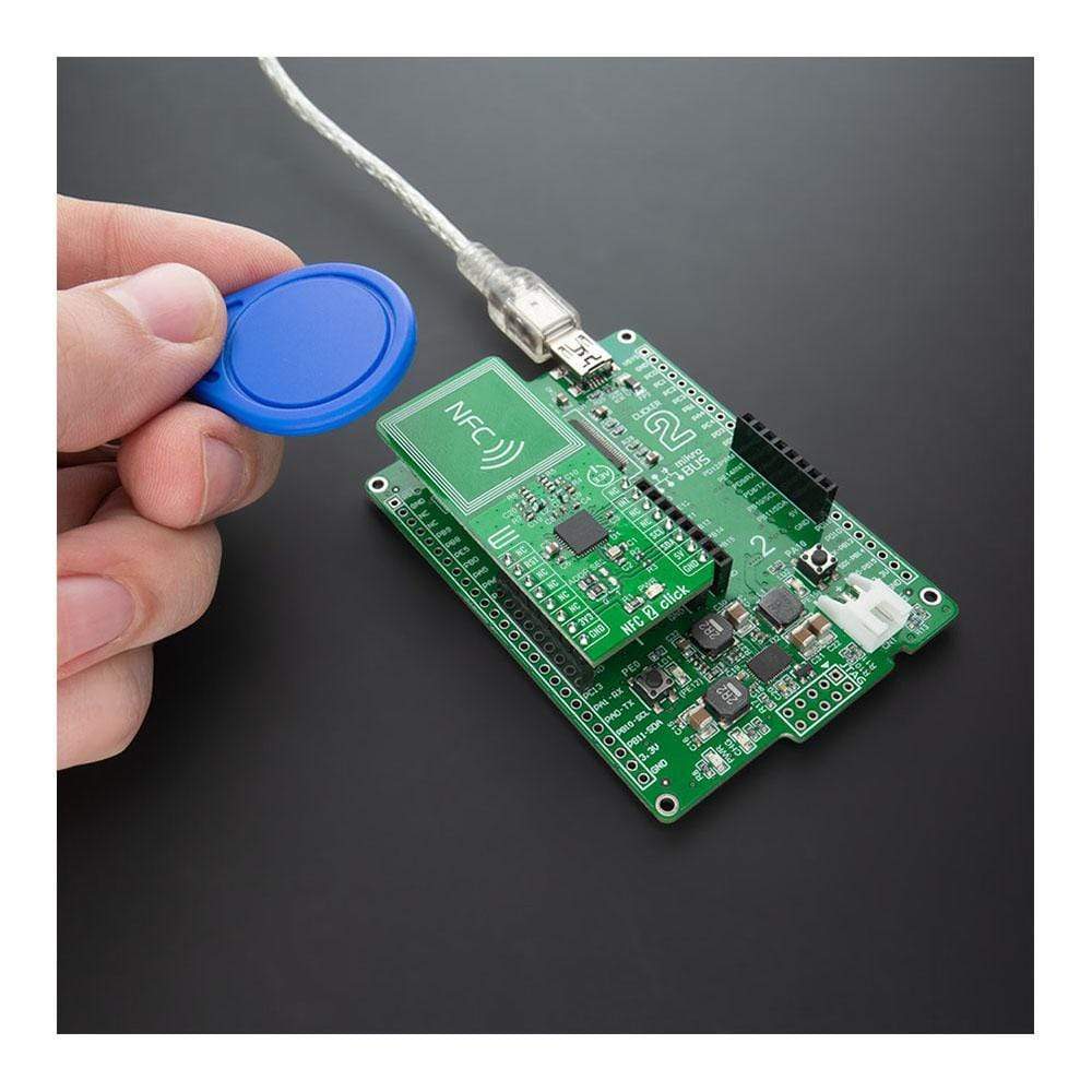
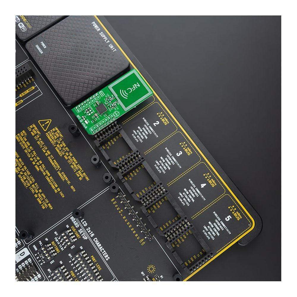
The NFC 2 Click Board™ is a compact add-on board that contains a highly integrated NFC transceiver for contactless communication. This board features the PN7150, the best plug&play high-performance full NFC solution with integrated firmware and NCI interface designed for contactless communication at 13.56 MHz from NXP USA Inc. This I2C configurable transceiver utilizes an outstanding modulation and demodulation concept completely integrated for different kinds of contactless communication methods and protocols. It can operate both in Reader Mode and in Card Mode. This Click Board™ is the ideal solution for rapidly integrating NFC technology in any application.
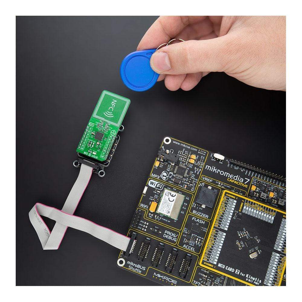
The NFC 2 Click Board™ is supported by a mikroSDK compliant library, which includes functions that simplify software development. This Click Board™ comes as a fully tested product, ready to be used on a system equipped with the mikroBUS™ socket.
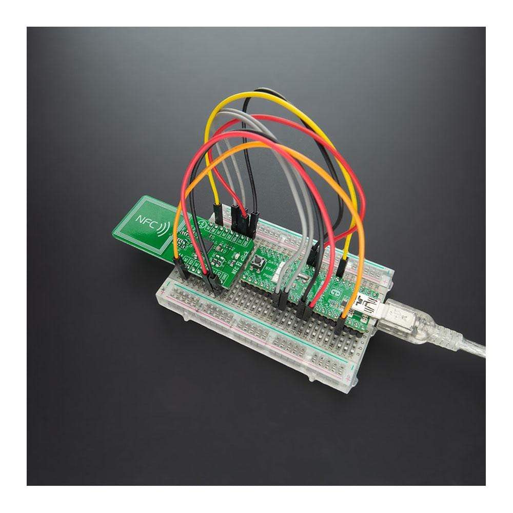
NOTE: Besides the Click board form factor, Mikroe offers a Dongle version also based on NXP’s PN7150 transceiver.
Downloads
Das NFC 2 Click Board™ ist eine kompakte Zusatzplatine, die einen hochintegrierten NFC-Transceiver für kontaktlose Kommunikation enthält. Diese Platine verfügt über den PN7150, die beste Plug&Play-Hochleistungs-NFC-Komplettlösung mit integrierter Firmware und NCI-Schnittstelle für kontaktlose Kommunikation bei 13,56 MHz von NXP USA Inc. Dieser I2C-konfigurierbare Transceiver verwendet ein hervorragendes Modulations- und Demodulationskonzept, das vollständig für verschiedene Arten von kontaktlosen Kommunikationsmethoden und -protokollen integriert ist. Er kann sowohl im Lesemodus als auch im Kartenmodus betrieben werden. Dieses Click Board™ ist die ideale Lösung für die schnelle Integration der NFC-Technologie in jede Anwendung.
Das NFC 2 Click Board™ wird von einer mikroSDK-kompatiblen Bibliothek unterstützt, die Funktionen enthält, die die Softwareentwicklung vereinfachen. Dieses Click Board™ wird als vollständig getestetes Produkt geliefert und ist bereit für den Einsatz auf einem System, das mit der mikroBUS™-Buchse ausgestattet ist.
HINWEIS: Neben dem Click-Board-Formfaktor bietet Mikroe auch eine Dongle-Version an, die auf dem PN7150-Transceiver von NXP basiert.
| General Information | |
|---|---|
Part Number (SKU) |
MIKROE-4309
|
Manufacturer |
|
| Physical and Mechanical | |
Weight |
0.018 kg
|
| Other | |
EAN |
8606027381294
|
Frequently Asked Questions
Have a Question?
Be the first to ask a question about this.