


Mikroelektronika d.o.o.
Strombegrenzungs-Click-Platine
Strombegrenzungs-Click-Platine
SKU: MIKROE-4271
Verfügbarkeit für Abholungen konnte nicht geladen werden


Overview
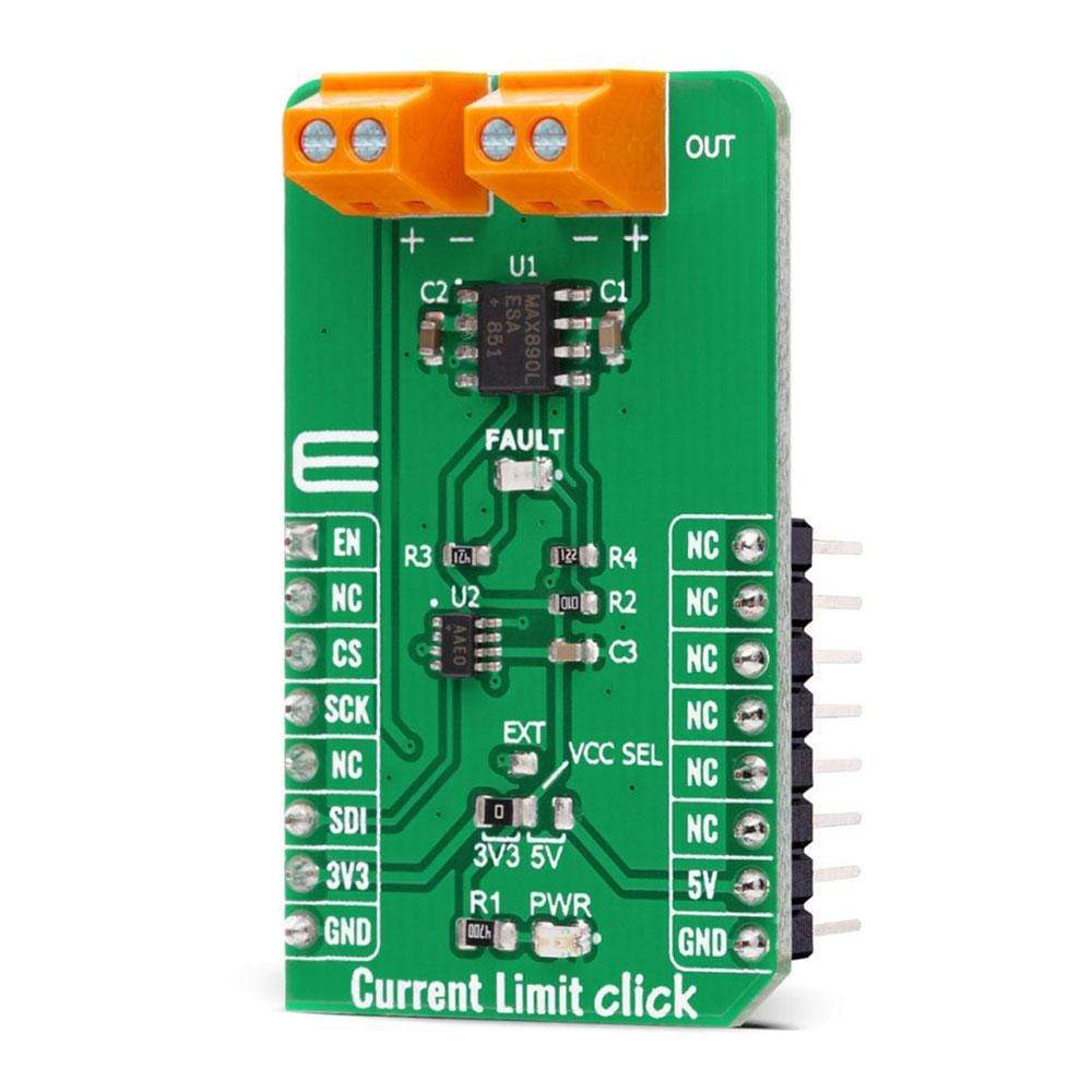
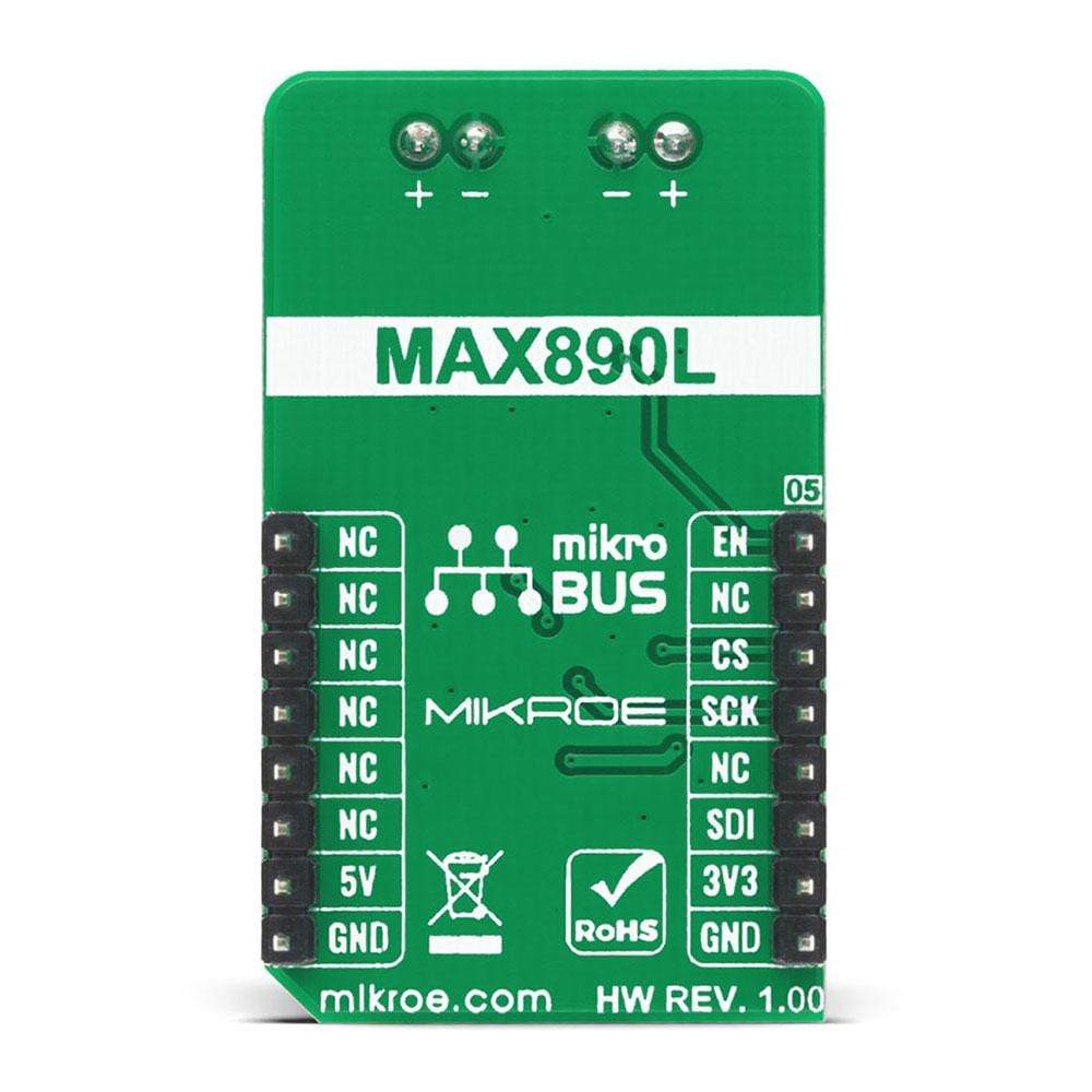
The Current Limit Click Board™ is a compact add-on board that contains a low-voltage, P-channel MOSFET power switch intended for high-side load switching applications. This board features the MAX890L, a low-resistance power switch with an adjustable, accurate current limit system, and thermal shutdown from Maxim Integrated. Its internal current-limiting circuitry protects the input supply against overload, while thermal protection limits power dissipation. The maximum current limit is 1.2A and can be programmed through a digital potentiometer MAX5401. The quiescent supply current has a low value of 10μA in the active state, while in its off state the supply current decreases to 0.1μA. This Click Board™ is suitable for applications in some portable equipment, access bus slots, or with power supplies, protecting them in cases of a short circuit or other overload conditions.
The Current Limit Click Board™ is supported by a mikroSDK compliant library, which includes functions that simplify software development. This Click Board™ comes as a fully tested product, ready to be used on a system equipped with the mikroBUS™ socket.
Downloads
Das Current Limit Click Board™ ist eine kompakte Zusatzplatine, die einen Niederspannungs-P-Kanal-MOSFET-Netzschalter enthält, der für High-Side-Lastschaltanwendungen vorgesehen ist. Diese Platine verfügt über den MAX890L, einen niederohmigen Netzschalter mit einem einstellbaren, genauen Strombegrenzungssystem und einer thermischen Abschaltung von Maxim Integrated. Seine interne Strombegrenzungsschaltung schützt die Eingangsversorgung vor Überlastung, während der thermische Schutz die Verlustleistung begrenzt. Die maximale Strombegrenzung beträgt 1,2 A und kann über ein digitales Potentiometer MAX5401 programmiert werden. Der Ruhestrom hat im aktiven Zustand einen niedrigen Wert von 10 μA, während im ausgeschalteten Zustand der Versorgungsstrom auf 0,1 μA abnimmt. Dieses Click Board™ ist für Anwendungen in einigen tragbaren Geräten, Zugangsbussteckplätzen oder mit Netzteilen geeignet und schützt sie bei Kurzschlüssen oder anderen Überlastbedingungen.
Das Current Limit Click Board™ wird von einer mikroSDK-kompatiblen Bibliothek unterstützt, die Funktionen enthält, die die Softwareentwicklung vereinfachen. Dieses Click Board™ wird als vollständig getestetes Produkt geliefert und ist bereit für den Einsatz auf einem System, das mit der mikroBUS™-Buchse ausgestattet ist.
| General Information | |
|---|---|
Part Number (SKU) |
MIKROE-4271
|
Manufacturer |
|
| Physical and Mechanical | |
Weight |
0.019 kg
|
| Other | |
EAN |
8606027380518
|
Frequently Asked Questions
Have a Question?
Be the first to ask a question about this.