


Mikroelektronika d.o.o.
LED-Treiber 8 Click-Platine
LED-Treiber 8 Click-Platine
SKU: MIKROE-4268
Verfügbarkeit für Abholungen konnte nicht geladen werden
Overview
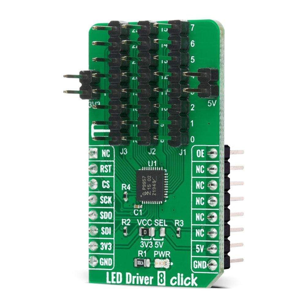
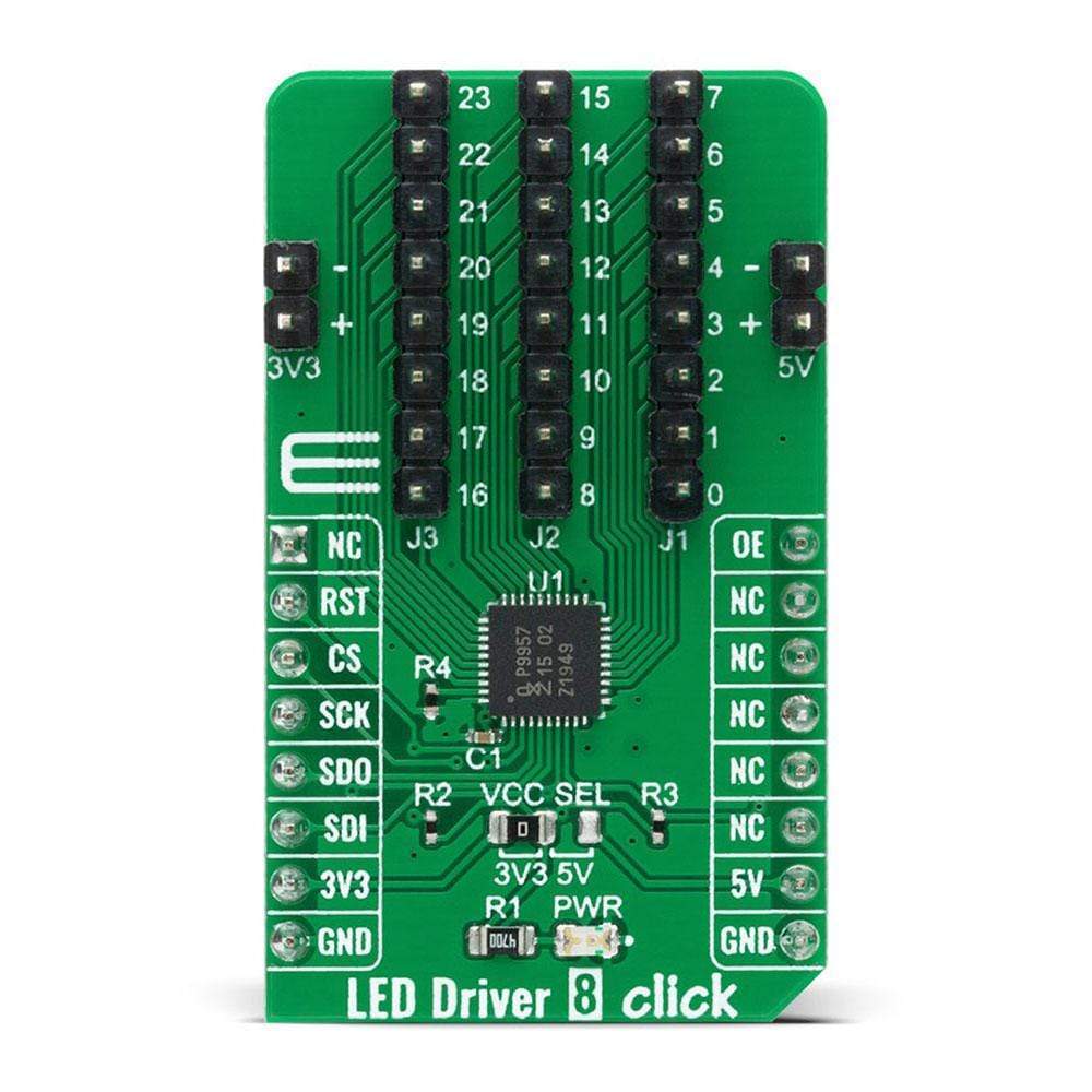
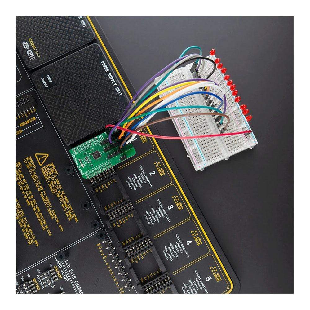
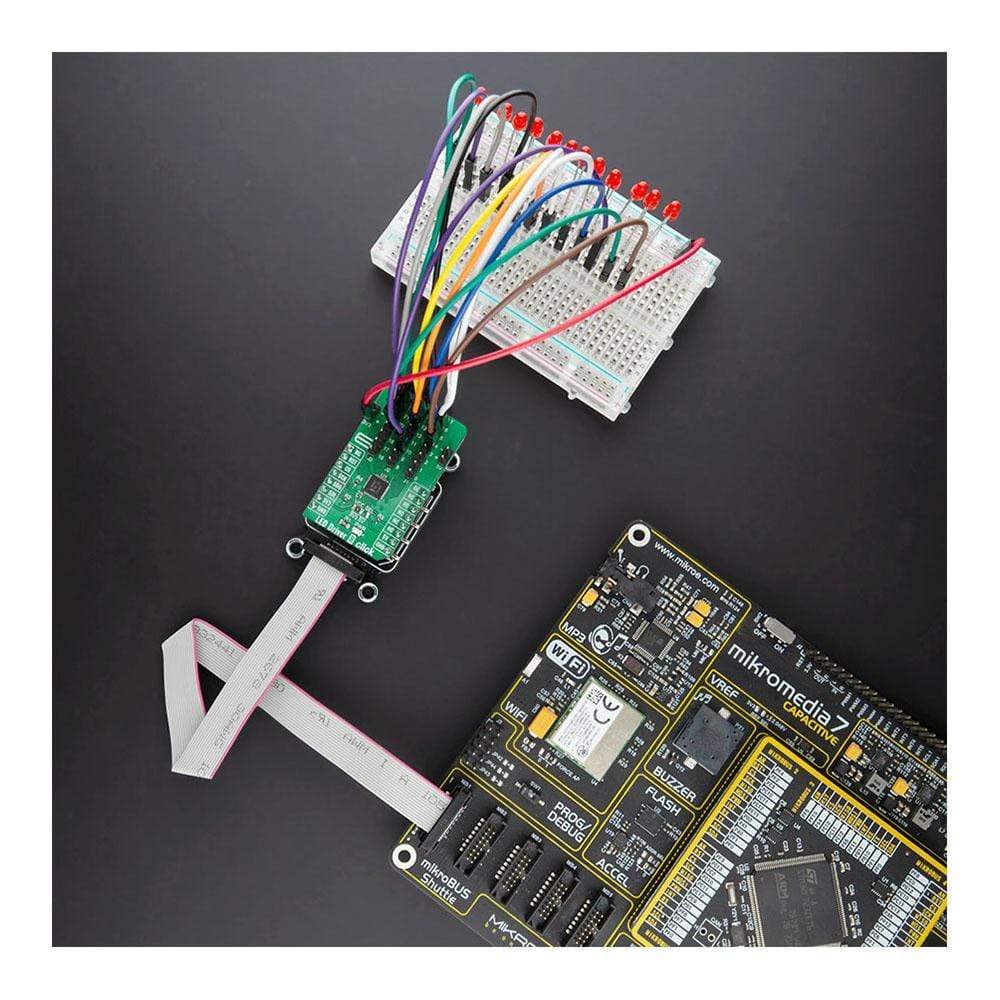
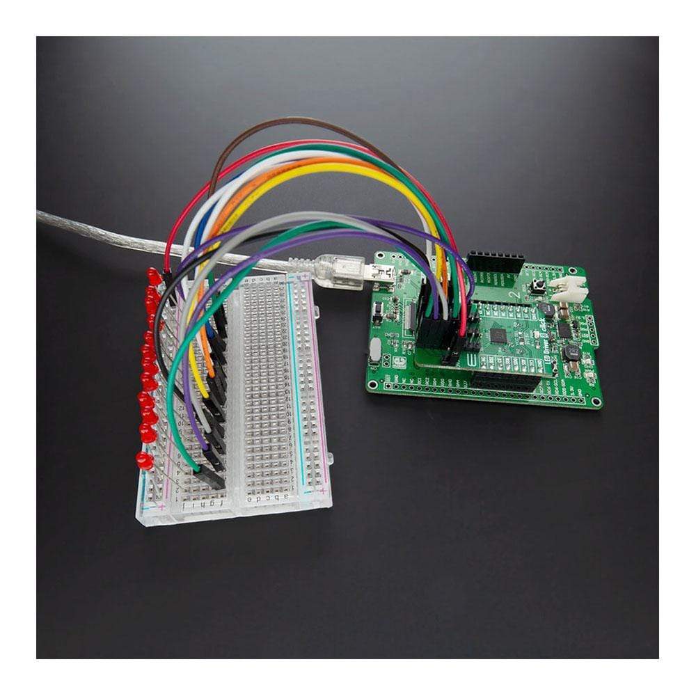
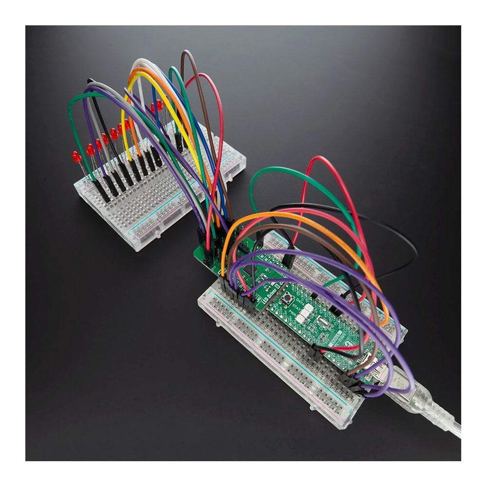
The LED Driver 8 Click Board™ is a compact add-on board optimized for dimming and blinking 32 mA RGBA LEDs. This board features the 24-channel SPI-compatible constant current LED driver from NXP Semiconductors. It has 24 LED output channels, a programmable group dimming/blinking mixed with individual LED brightness, and programmable LED output delay to reduce EMI and surge currents. It also possesses gradation control for all channels where all 24 constant current output channels can sink up to 32 mA, and tolerate up to 5.5 V in its OFF state. As the name itself says, this Click Board™, next to driving RGBA LEDs can be used for the purpose of LED Status signalization in LED displays, LED backlight, keypad backlights for cellular phones or handheld devices, and many more.
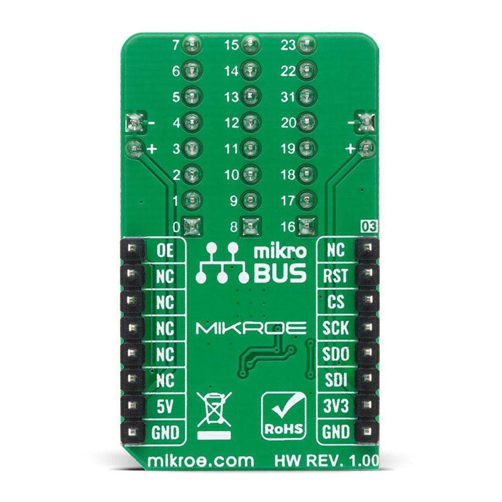
The LED Driver 8 Click Board™ is supported by a mikroSDK compliant library, which includes functions that simplify software development. This Click Board™ comes as a fully tested product, ready to be used on a system equipped with the mikroBUS™ socket.
Downloads
Der LED-Treiber 8 Click Board™ ist eine kompakte Zusatzplatine, die zum Dimmen und Blinken von 32 mA RGBA-LEDs optimiert ist. Diese Platine verfügt über den 24-Kanal-SPI-kompatiblen Konstantstrom-LED-Treiber von NXP Semiconductors. Sie verfügt über 24 LED-Ausgangskanäle, eine programmierbare Gruppendimmung/-blinken gemischt mit individueller LED-Helligkeit und eine programmierbare LED-Ausgangsverzögerung zur Reduzierung von elektromagnetischen Störungen und Stoßströmen. Sie verfügt außerdem über eine Abstufungssteuerung für alle Kanäle, wobei alle 24 Konstantstrom-Ausgangskanäle bis zu 32 mA aufnehmen und im AUS-Zustand bis zu 5,5 V tolerieren können. Wie der Name schon sagt, kann dieses Click Board™ neben dem Ansteuern von RGBA-LEDs auch zur LED-Statussignalisierung in LED-Anzeigen, LED-Hintergrundbeleuchtung, Tastatur-Hintergrundbeleuchtung für Mobiltelefone oder Handheld-Geräte und vielem mehr verwendet werden.
Das LED-Treiber 8 Click Board™ wird durch eine mikroSDK-kompatible Bibliothek unterstützt, die Funktionen enthält, die die Softwareentwicklung vereinfachen. Dieses Click Board™ wird als vollständig getestetes Produkt geliefert und ist bereit für den Einsatz auf einem System, das mit der mikroBUS™-Buchse ausgestattet ist.
| General Information | |
|---|---|
Part Number (SKU) |
MIKROE-4268
|
Manufacturer |
|
| Physical and Mechanical | |
Weight |
0.019 kg
|
| Other | |
EAN |
8606027380440
|
Frequently Asked Questions
Have a Question?
Be the first to ask a question about this.