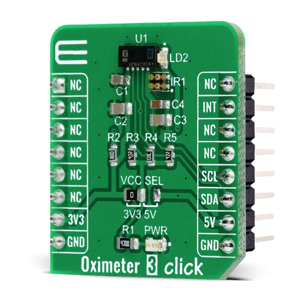
Oximeter 3 Click-Platine
Overview
Das Oximeter 3 Click Board™ ist eine kompakte Zusatzplatine, die sich perfekt zum Messen der Blutsauerstoffsättigung eignet. Diese Platine verfügt über den VCNL4020C-GS08, einen vollständig integrierten hochauflösenden digitalen Biosensor von Vishay Semiconductors. Er kombiniert einen Infrarot-Emitter und eine PIN-Fotodiode für Biosensorfunktionalität, einen Umgebungslichtsensor und einen Signalverarbeitungs-IC in einem einzigen Gehäuse mit einem 16-Bit-ADC. Er unterstützt eine standardmäßige serielle digitale I2C-Schnittstelle und verfügt über die programmierbare Interrupt-Funktion, die eine Weckfunktion bietet, wenn ein Näherungsereignis oder eine Änderung des Umgebungslichts auftritt. Dieses Click Board™ ist eine ausgezeichnete Wahl für Anwendungen wie optische Pulsoximetrie und Gesundheitsüberwachung.
Das Oximeter 3 Click Board™ wird von einer mikroSDK-kompatiblen Bibliothek unterstützt, die Funktionen enthält, die die Softwareentwicklung vereinfachen. Dieses Click Board™ wird als vollständig getestetes Produkt geliefert und ist bereit für den Einsatz auf einem System, das mit der mikroBUS™-Buchse ausgestattet ist.
How Does The Oximeter 3 Click Board™ Work?
The Oximeter 3 Click Board™ is based on the VCNL4020C-GS08, a fully integrated biosensor and ambient light sensor with an I2C interface from Vishay Semiconductor. The VCNL4020C-GS08 sensor comes with a built-in infrared emitter, and signal processing IC in a single package with a 16 bit ADC. It also has an ambient light PIN photodiode with close-to-human-eye sensitivity with excellent ambient light suppression through signal modulation. For biosensor functionality, it converts the current from the PIN photodiode to a 16-bit digital data output value, while for the ambient light sensing it converts the current from the ambient light detector, amplifies it, and converts it to a 16-bit digital output stream.
The integrated infrared emitter has a peak wavelength of 890 nm. It emits light that reflects off an object within 20 cm of the sensor and has a programmable drive current from 10 mA to 200 mA in 10 mA steps. The built-in infrared emitter and broader sensitivity photodiode also can work with the additional on-board green LED and IRLED as designed on this Click board™. As an additional light source true green color LED (VLMTG1300) with a 525nm peak wavelength is used, alongside an infrared dual-color emitting diode (VSMD66694) with 660 nm and 940 nm peak wavelength well suited for measuring the optical pulse oximetry.
The PIN photodiode receives the light that is reflected off the object and converts it to a current. It has a peak sensitivity of 890 nm, matching the peak wavelength of the emitter, and it is insensitive to ambient light. The VCNL4020C also provides ambient light sensing to support conventional backlight and display brightness auto-adjustment. The ambient light sensor receives the visible light and converts it to a current, and it has peak sensitivity at 540 nm and bandwidth from 430 nm to 610 nm.
The Oximeter 3 Click Board™ communicates with the MCU using the standard I2C 2-wire interface with fixed slave address compatible with all I2C modes (Standard, Fast, and High-Speed). It allows easy access to a biosensor signal and light intensity measurements without complex calculations or programming. It also generates programmable interrupt signal routed on the INT pin of the mikroBUS™, that offers Wake-Up functionality for the MCU when a proximity event or ambient light change occurs, which reduces processing overhead by eliminating the need for continuous polling.
The Oximeter 3 Click Board™ is designed to be operated with both 3.3V and 5V logic voltage levels that can be selected via VCC SEL jumper. This allows for both 3.3V and 5V capable MCUs to use the I2C communication lines properly.
SPECIFICATIONS
Type | Biometrics |
Applications | Can be used for applications such as optical pulse oximetry and health monitoring. |
On-board modules | The Oximeter 3 Click Board™ is based on the VCNL4020C-GS08, a fully integrated biosensor and ambient light sensor with an I2C interface from Vishay Semiconductor. |
Key Features | Low current consumption, onboard LEDs optimized for the oximetry measurements, high frequency bursts for biosensor signal measurement, programmable interrupt function, and more. |
Interface | I2C |
Compatibility | mikroBUS |
Click board size | S (28.6 x 25.4 mm) |
Input Voltage | 3.3V or 5V |
PINOUT DIAGRAM
This table shows how the pinout of the Oximeter 3 Click Board™ corresponds to the pinout on the mikroBUS™ socket (the latter shown in the two middle columns).
Notes | Pin | Pin | Notes | ||||
---|---|---|---|---|---|---|---|
NC | 1 | AN | PWM | 16 | NC | ||
NC | 2 | RST | INT | 15 | INT | Interrupt | |
NC | 3 | CS | RX | 14 | NC | ||
NC | 4 | SCK | TX | 13 | NC | ||
NC | 5 | MISO | SCL | 12 | SCL | I2C Clock | |
NC | 6 | MOSI | SDA | 11 | SDA | I2C Data | |
Power Supply | 3.3V | 7 | 3.3V | 5V | 10 | 5V | Power Supply |
Ground | GND | 8 | GND | GND | 9 | GND | Ground |
ONBOARD SETTINGS AND INDICATORS
Label | Name | Default | Description |
---|---|---|---|
LD1 | PWR | - | Power LED Indicator |
LD2 | VLMTG1300 | - | Green Measurement LED |
IR1 | VSMD66694 | - | Infrared Measurement LED |
JP1 | VCC SEL | Left | Power Supply Voltage Selection 3V3/5V: Left position 3V3, Right position 5V |
OXIMETER 3 CLICK ELECTRICAL SPECIFICATIONS
Description | Min | Typ | Max | Unit |
---|---|---|---|---|
Supply Voltage | -0.3 | - | 5.5 | V |
Ambient Light Resolution | - | 0.25 | - | Ik |
IR1 Infrared Wavelenght | 660 | - | 940 | nm |
LD2 Green LED Wavelenght | - | 525 | - | nm |
Operating Temperature Range | -25 | - | +85 | V |
Software Support
We provide a library for the Oximeter 3 Click Board™ on our LibStock page, as well as a demo application (example), developed using MikroElektronika compilers. The demo can run on all the main MikroElektronika development boards.
Library Description
Library provides generic functions for reading and writing data to register and getting INT pin status. There is one specific function that reads data from sensor and returns it, which data returns depends on input parameter.
Key Functions
void oximeter3_generic_write ( uint8_t reg_addr, uint8_t write_data )
- Function for writing data to register address.uint8_t oximeter3_generic_read ( uint8_t reg_addr )
- Function for reading data from register address.uint16_t oximeter3_read_value ( uint8_t type_macro )
- Function for reading value from sensor.
Example Description
The application is composed of three sections :
- System Initialization - Initialization of I2C module and int pin
- Application Initialization - Check id status, configures device for previous selected mode
- Application Task - Application measures values of heart rate or proximity and als value. It depends of selected device mode.
void application_task ( ) { if ( OXIMETER3_HEART_RATE == dev_mode ) { rd_val = oximeter3_read_value( OXIMETER3_PROX ); WordToStr( rd_val, demo_txt ); mikrobus_logWrite( demo_txt, _LOG_TEXT ); mikrobus_logWrite( ",", _LOG_LINE ); Delay_ms( 3 ); } else { rd_val = oximeter3_read_value( OXIMETER3_PROX ); WordToStr( rd_val, demo_txt ); mikrobus_logWrite( " * Proximity: ", _LOG_TEXT ); mikrobus_logWrite( demo_txt, _LOG_LINE ); rd_val = oximeter3_read_value( OXIMETER3_ALS ); WordToStr( rd_val, demo_txt ); mikrobus_logWrite( " * ALS: ", _LOG_TEXT ); mikrobus_logWrite( demo_txt, _LOG_LINE ); mikrobus_logWrite( "********************", _LOG_LINE ); Delay_ms( 500 ); } }
The full application code, and ready to use projects can be found on our LibStock page.
Other mikroE Libraries used in the example:
- I2C
- UART
- Conversions
Additional Notes and Information
Depending on the development board you are using, you may need USB UART Click Board™, USB UART 2 Click Board™ or RS232 Click Board™ to connect to your PC, for development systems with no UART to USB interface available on the board. The terminal available in all MikroElektronika compilers, or any other terminal application of your choice, can be used to read the message.
MIKROSDK
The Oximeter 3 Click Board™ is supported with mikroSDK - MikroElektronika Software Development Kit. To ensure proper operation of mikroSDK compliant Click board™ demo applications, mikroSDK should be downloaded from the LibStock and installed for the compiler you are using.
Frequently Asked Questions
Have a Question?
Be the first to ask a question about this.