


Mikroelektronika d.o.o.
I2C Extend Click-Platine
I2C Extend Click-Platine
SKU: MIKROE-4207
Verfügbarkeit für Abholungen konnte nicht geladen werden
Overview
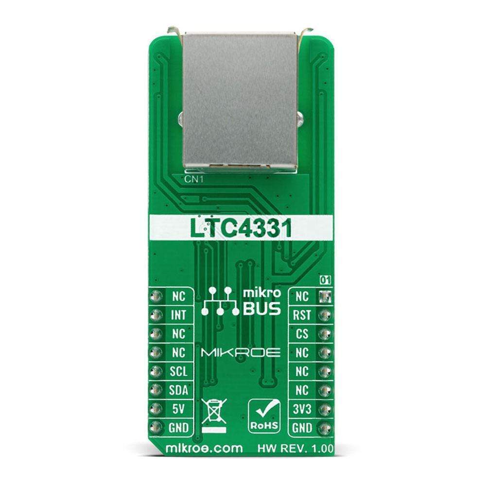
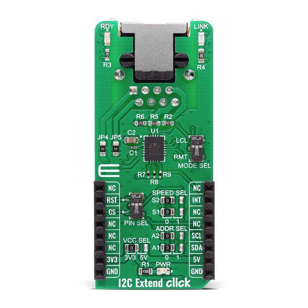
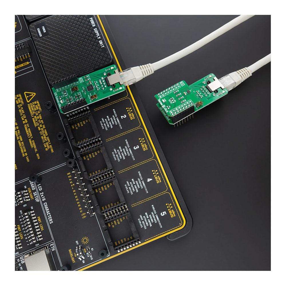
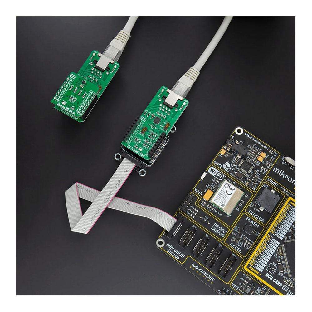
The I2C Extend Click Board™ is a compact add-on board for applications that require extending the I2C communication bus over a long distance. This board features the LTC4331 - an I2C slave device extender over a rugged differential link, from Analog Devices. It is a point-to-point SMBus compatible I2C slave device extender, designed for operation in high noise industrial environments while supporting Up to 1MHz serial clock, ±40kV ESD protection on link pins, selectable link baud rates and many more. All these features make I2C Extend Click an excellent choice for various applications that require extending the I2C bus over a long distance, such as sensor installation, industrial control, lighting system control, sound system control, and more.
The I2C Extend Click Board™ is supported by a mikroSDK compliant library, which includes functions that simplify software development. This Click Board™ comes as a fully tested product, ready to be used on a system equipped with the mikroBUS™ socket.
Downloads
Das I2C Extend Click Board™ ist eine kompakte Zusatzplatine für Anwendungen, bei denen der I2C-Kommunikationsbus über eine große Distanz verlängert werden muss. Diese Platine verfügt über den LTC4331 – einen I2C-Slave-Geräte-Extender über eine robuste Differenzialverbindung von Analog Devices. Es handelt sich um einen Punkt-zu-Punkt-SMBus-kompatiblen I2C-Slave-Geräte-Extender, der für den Betrieb in geräuschintensiven Industrieumgebungen entwickelt wurde und bis zu 1 MHz seriellen Takt, ±40 kV ESD-Schutz an Verbindungsstiften, wählbare Verbindungs-Baudraten und vieles mehr unterstützt. All diese Funktionen machen I2C Extend Click zu einer ausgezeichneten Wahl für verschiedene Anwendungen, bei denen der I2C-Bus über eine große Distanz verlängert werden muss, wie z. B. Sensorinstallation, Industriesteuerung, Beleuchtungssystemsteuerung, Soundsystemsteuerung und mehr.
Das I2C Extend Click Board™ wird von einer mikroSDK-kompatiblen Bibliothek unterstützt, die Funktionen enthält, die die Softwareentwicklung vereinfachen. Dieses Click Board™ wird als vollständig getestetes Produkt geliefert und ist bereit für den Einsatz auf einem System, das mit der mikroBUS™-Buchse ausgestattet ist.
| General Information | |
|---|---|
Part Number (SKU) |
MIKROE-4207
|
Manufacturer |
|
| Physical and Mechanical | |
Weight |
0.023 kg
|
| Other | |
EAN |
8606027380181
|
Frequently Asked Questions
Have a Question?
Be the first to ask a question about this.