


Mikroelektronika d.o.o.
DotMatrix R Click-Platine
DotMatrix R Click-Platine
SKU: MIKROE-4169
Verfügbarkeit für Abholungen konnte nicht geladen werden


Overview
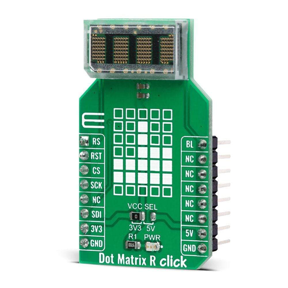
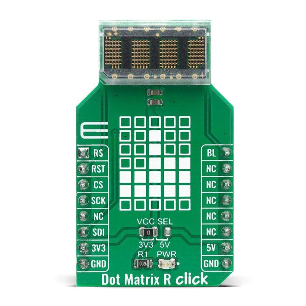
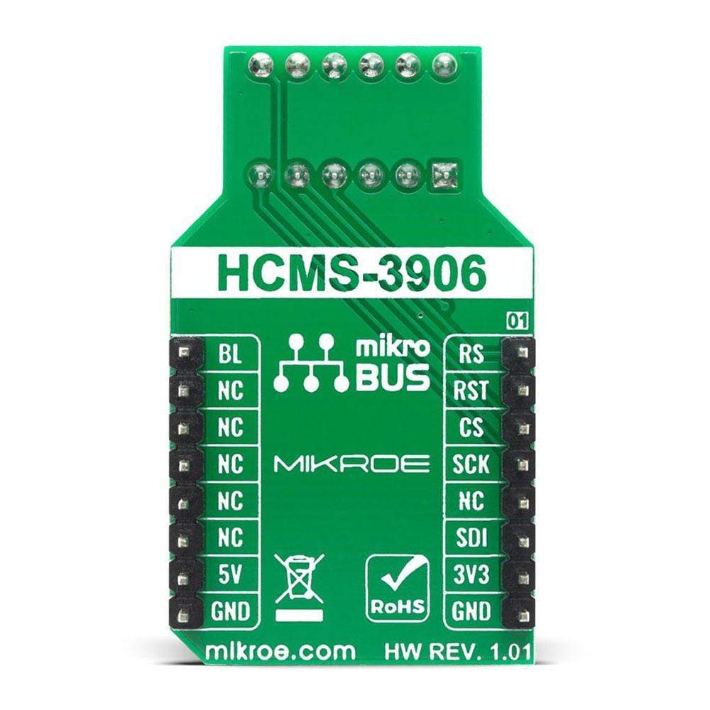
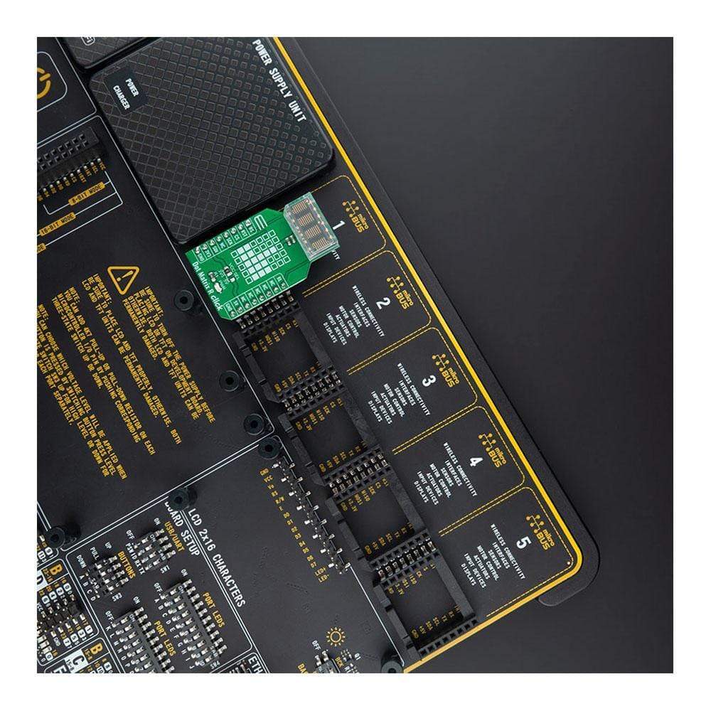
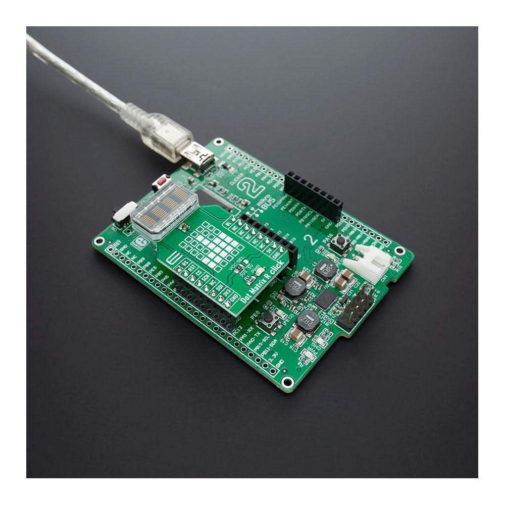
The Dot Matrix R Click Board™ is a display device based on a four-digit dot matrix display module, labelled as HCMS-3906 from a company Avago (Broadcom Inc). The module holds four 5x7 dot matrices, with very closely spaced, bright red pixel elements. Characters are very clearly displayed as a result. Pixels emit a bright red colour when lit, which makes the display readable in any condition. Each display can be directly interfaced with a microprocessor, thus eliminating the need for cumbersome interface components.
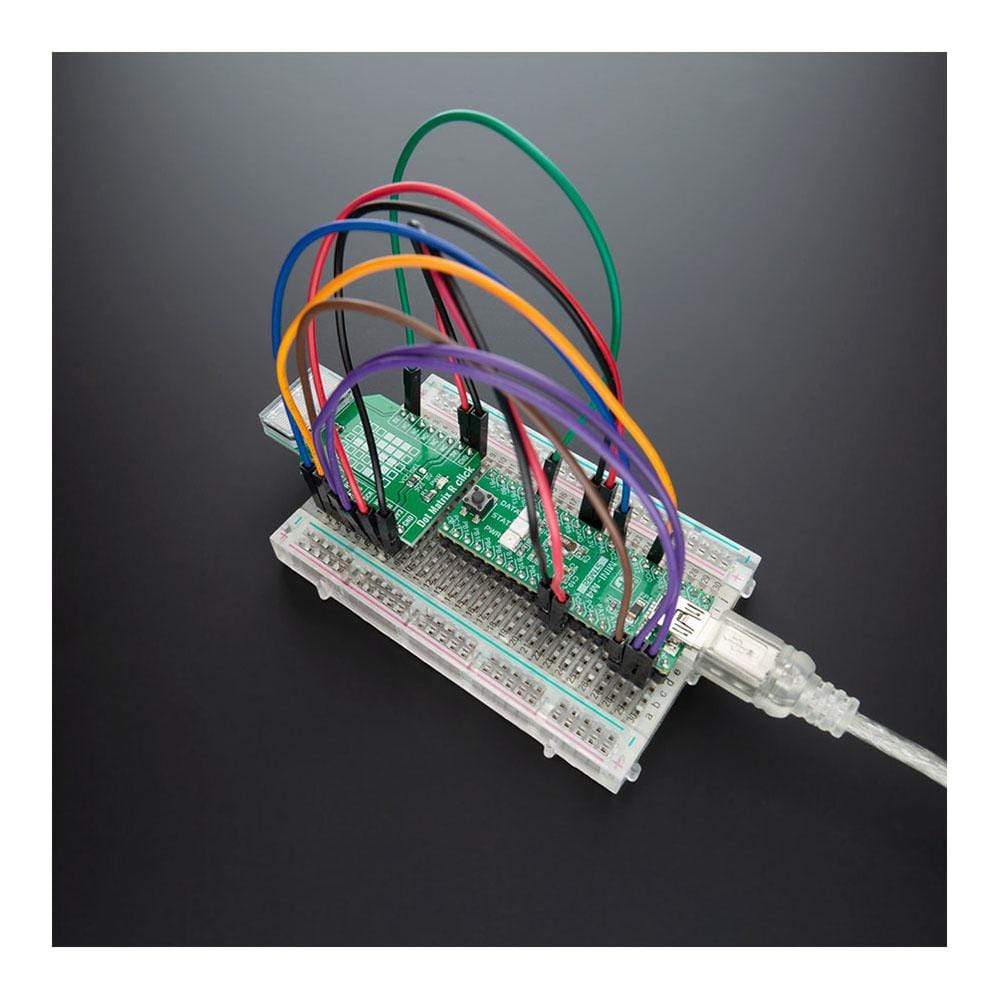
The serial IC interface allows higher character count information displays with a minimum of data lines. The easy to read 5x7 pixel format allows the display of upper case, lower case, Katakana, and custom user-defined characters. The bright red display matrix has a wide viewing range, which makes it perfectly suited for low light situations.
Downloads
Das Dot Matrix R Click Board™ ist ein Anzeigegerät auf Basis eines vierstelligen Punktmatrix-Anzeigemoduls mit der Bezeichnung HCMS-3906 von Avago (Broadcom Inc.). Das Modul enthält vier 5x7-Punktmatrizen mit sehr eng beieinander liegenden, leuchtend roten Pixelelementen. Dadurch werden Zeichen sehr deutlich angezeigt. Wenn Pixel leuchten, strahlen sie eine leuchtend rote Farbe aus, wodurch die Anzeige unter allen Bedingungen lesbar ist. Jede Anzeige kann direkt mit einem Mikroprozessor verbunden werden, wodurch die Notwendigkeit umständlicher Schnittstellenkomponenten entfällt.
Die serielle IC-Schnittstelle ermöglicht die Anzeige von Informationen mit einer höheren Zeichenanzahl bei minimalen Datenleitungen. Das leicht lesbare 5x7-Pixelformat ermöglicht die Anzeige von Großbuchstaben, Kleinbuchstaben, Katakana und benutzerdefinierten Zeichen. Die leuchtend rote Anzeigematrix hat einen großen Sichtbereich und ist daher perfekt für Situationen mit schlechten Lichtverhältnissen geeignet.
| General Information | |
|---|---|
Part Number (SKU) |
MIKROE-4169
|
Manufacturer |
|
| Physical and Mechanical | |
Weight |
0.019 kg
|
| Other | |
EAN |
8606018717897
|
Frequently Asked Questions
Have a Question?
Be the first to ask a question about this.