Force 3 Click-Platine
Overview
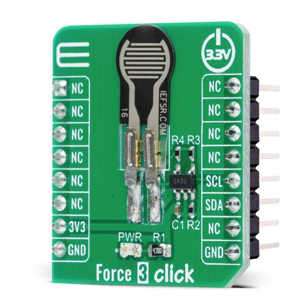
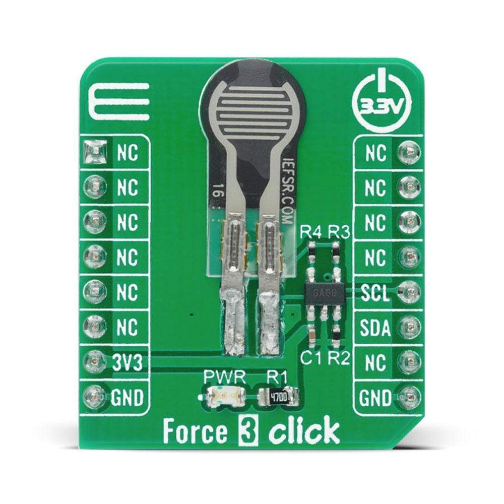
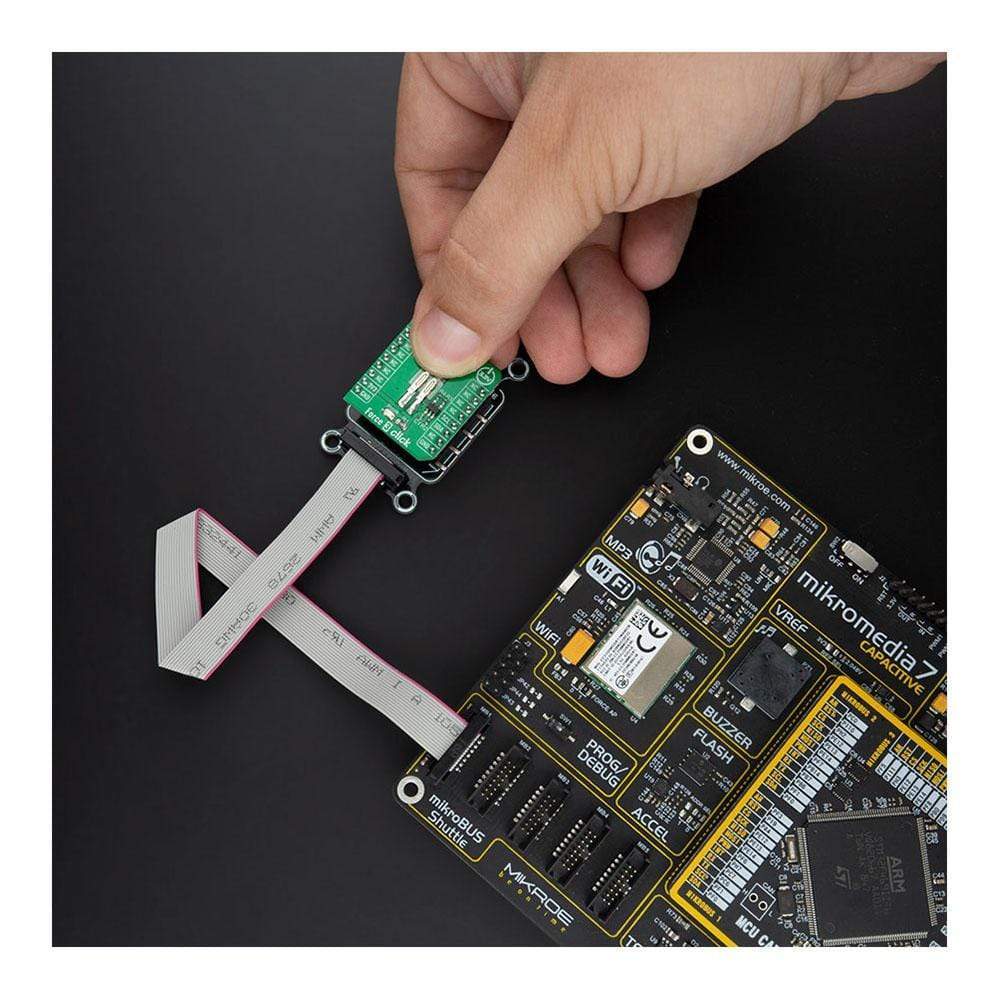
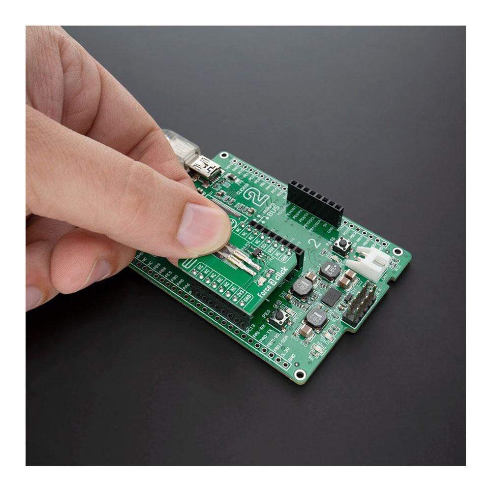
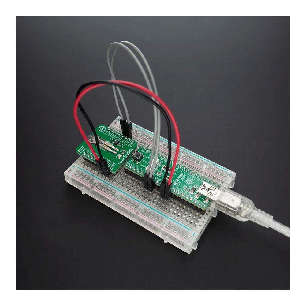
Das Force 3 Click Board™ ist eine kompakte Zusatzplatine mit Schaltkreisen zur Implementierung eines Force Sensing Resistor in Ihre Projekte, dessen Widerstand sich ändert, wenn eine Kraft, ein Druck oder eine mechanische Belastung ausgeübt wird. Diese Platine verfügt über einen Einzelzonen-Force Sensing Resistor der FSR 400-Serie 34-00004 von Interlink Electronics, ein robustes Polymer-Dickschichtgerät (PTF), dessen Widerstand bei zunehmender auf die Oberfläche des Sensors ausgeübter Kraft abnimmt. Force 3 Click ist einfach und leicht zu integrieren, ultradünn und kostengünstig und verfügt über eine Betätigungskraft von nur 0,2 N und einen Empfindlichkeitsbereich von bis zu 20 N. Es bietet außerdem eine 2-adrige I2C-kompatible Steuerschnittstelle mit einem MCP3221, einem stromsparenden A/D-Wandler mit 12-Bit-Auflösung. Dieses Click Board™ ist für den Einsatz in Mensch-Maschine-Schnittstellengeräten optimiert, einschließlich Automobilelektronik, medizinischen Systemen, industriellen Steuerungen und Robotik.
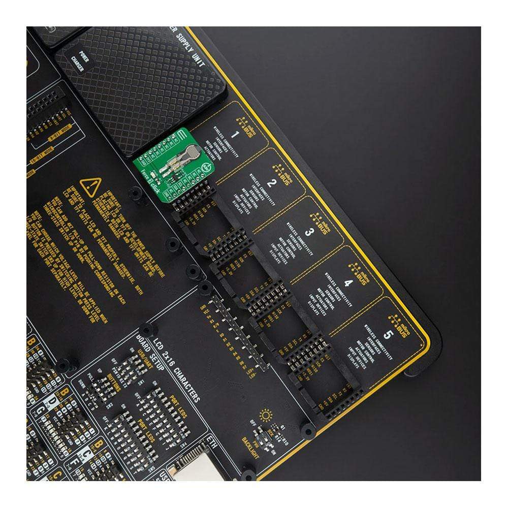
Das Force 3 Click Board™ wird von einer mikroSDK-kompatiblen Bibliothek unterstützt, die Funktionen enthält, die die Softwareentwicklung vereinfachen. Dieses Click Board™ wird als vollständig getestetes Produkt geliefert und ist bereit für den Einsatz auf einem System, das mit der mikroBUS™-Buchse ausgestattet ist.
How Does The Force 3 Click Board™ Work?
The Force 3 Click Board™ is based on the FSR 400 series 34-00004 single zone Force Sensing Resistor IC from Interlink Electronics. Force-sensing resistors consist of a conductive polymer, which predictably changes resistance following the application of force to its surface. As the force on the sensor is increased, the resistance is decreased. This thin sensor is made of two membranes that are separated by a spacer around the edges. The top layer of the sensor consists of the area of the force-sensitive layer on the flexible film, while the bottom layer is comprised of conductive circuit traces on the flexible film. When pressed, the gap between the two membranes gets closed. This shorts the two membranes together, with a resistance that is proportional to an applied force.
The Force 3 Click Board™ also contains all the necessary circuitry, required to obtain precise measurements from the sensor. It communicates with the MCU using the MCP3221, low-power 12-bit resolution A/D converter with an I2C interface. Data on the I2C-bus can be transferred at rates of up to 100 kbit/s in the Standard-mode and up to 400 kbit/s in the Fast-mode. Maximum sample rates of 22.3 kSPS are possible with the MCP3221 in a continuous-conversion mode and SCL clock rate of 400 kHz.
The sensor is placed in a voltage divider configuration with a fixed resistor R2 (10k). The output voltage is measured across resistor R2 and then sent to the analog pin of the A/D converter MCP3221. Output voltage value was calculated using the voltage divider formula, whose value is later used in the Test Example to accurately determine the strength of the applied force. The Test Example is made in such a way that, based on the value of the applied force, it is possible to obtain four output values such as Light Touch, Weak Squeeze, Medium Squeeze, and Strong Squeeze.
The Force 3 Click Board™ uses the I2C communication interface. It is designed to be operated only with 3.3V logic levels. A proper logic voltage level conversion should be performed before the Click board™ is used with MCUs with logic levels of 5V. More information about the 34-00004 Force Sensing Resistor can be found in the attached datasheet. However, the Click board™ comes equipped with a library that contains easy to use functions and a usage example that may be used as a reference for the development.
SPECIFICATIONS
Type | Force |
Applications | The Force 3 Click Board™ be used in human-machine interface devices including automotive electronics, medical systems, industrial controls, and robotics. |
On-board modules | Force 3 Click is based on the FSR 400 series 34-00004 single zone Force Sensing Resistor IC from Interlink Electronics. |
Key Features | Low actuation force, wide sensitivity range, low power consumption, quick response, and more. |
Interface | I2C |
Compatibility | mikroBUS |
Click board size | S (28.6 x 25.4 mm) |
Input Voltage | 3.3V |
PINOUT DIAGRAM
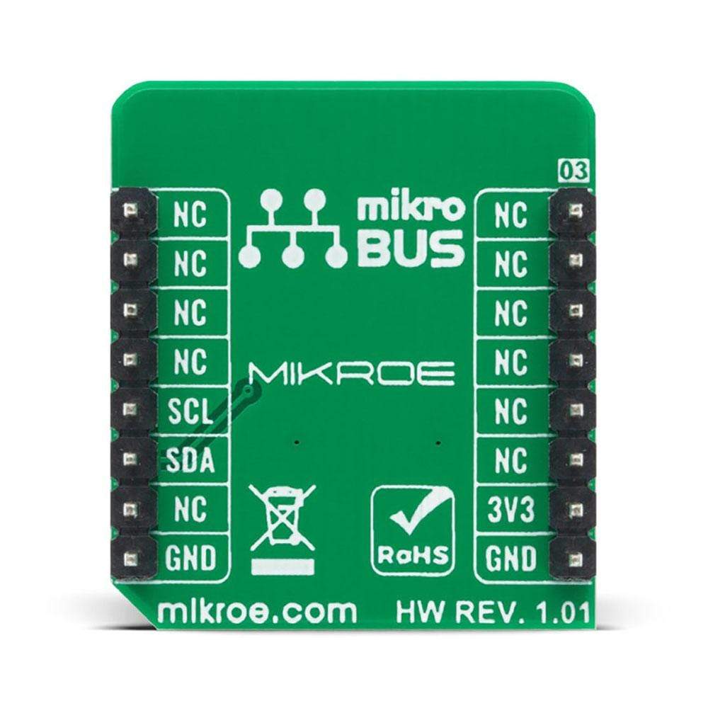
This table shows how the pinout of the Force 3 Click Board™ corresponds to the pinout on the mikroBUS™ socket (the latter shown in the two middle columns).
Notes | Pin | Pin | Notes | ||||
---|---|---|---|---|---|---|---|
NC | 1 | AN | PWM | 16 | NC | ||
NC | 2 | RST | INT | 15 | NC | ||
NC | 3 | CS | RX | 14 | NC | ||
NC | 4 | SCK | TX | 13 | NC | ||
NC | 5 | MISO | SCL | 12 | SCL | I2C Clock | |
NC | 6 | MOSI | SDA | 11 | SDA | I2C Data | |
Power Supply | 3.3V | 7 | 3.3V | 5V | 10 | NC | |
Ground | GND | 8 | GND | GND | 9 | GND | Ground |
ONBOARD SETTINGS AND INDICATORS
Label | Name | Default | Description |
---|---|---|---|
LD1 | PWR | - | Power LED Indicator |
FORCE 3 CLICK ELECTRICAL SPECIFICATIONS
Description | Min | Typ | Max | Unit |
---|---|---|---|---|
Supply Voltage | - | 3.3 | - | V |
Actuation Force | 0.2 | - | - | N |
Force Sensing Range | 0.2 | - | 20 | N |
Response Time | - | <10 | - | μs |
Operating Temperature Range | -40 | - | +85 | °C |
Software Support
We provide a library for the Force 3 Click Board™ on our LibStock page, as well as a demo application (example), developed using MikroElektronika compilers. The demo can run on all the main MikroElektronika development boards.
Library Description
The library contains basic functions for working with the Force 3 Click Board™.
Key Functions
uint16_t force3_read_raw_data( )
- Read 12bit raw data
Example Description
The application is composed of three sections :
- System Initialization - Initializes I2C module
- Application Initialization - Initializes driver init
- Application Task - Reads sensor raw data and shows the pressure on the sensor.
void application_task ( ) { uint16_t raw_data; char demo_text[ 20 ]; raw_data = force3_read_raw_data(); IntToStr( raw_data, demo_text ); mikrobus_logWrite( "Raw data: ", _LOG_TEXT ); mikrobus_logWrite( demo_text, _LOG_LINE ); if ( ( raw_data > 15 ) && ( raw_data <= 200 ) ) { mikrobus_logWrite( ">> Light touch", _LOG_LINE ); } else if ( ( raw_data > 200 ) && ( raw_data <= 500 ) ) { mikrobus_logWrite( ">> Light squeeze", _LOG_LINE ); } else if ( ( raw_data > 500 ) && ( raw_data <= 800 ) ) { mikrobus_logWrite( ">> Medium squeeze", _LOG_LINE ); } else if ( raw_data > 800 ) { mikrobus_logWrite( ">> Big squeeze", _LOG_LINE ); } mikrobus_logWrite( "----------------------", _LOG_LINE ); Delay_ms( 1500 ); }
The full application code, and ready to use projects can be found on our LibStock page.
Other mikroE Libraries used in the example:
- I2C Library - Conversions Library
Additional Notes and Information
Depending on the development board you are using, you may need USB UART Click Board™, USB UART 2 Click Board™ or RS232 Click Board™ to connect to your PC, for development systems with no UART to USB interface available on the board. The terminal available in all MikroElektronika compilers, or any other terminal application of your choice, can be used to read the message.
MIKROSDK
The Force 3 Click Board™ is supported with mikroSDK - MikroElektronika Software Development Kit. To ensure proper operation of mikroSDK compliant Click board™ demo applications, mikroSDK should be downloaded from the LibStock and installed for the compiler you are using.
Frequently Asked Questions
Have a Question?
Be the first to ask a question about this.