


Mikroelektronika d.o.o.
H-Bridge 7 Click-Platine
H-Bridge 7 Click-Platine
SKU: MIKROE-4143
Verfügbarkeit für Abholungen konnte nicht geladen werden
Overview
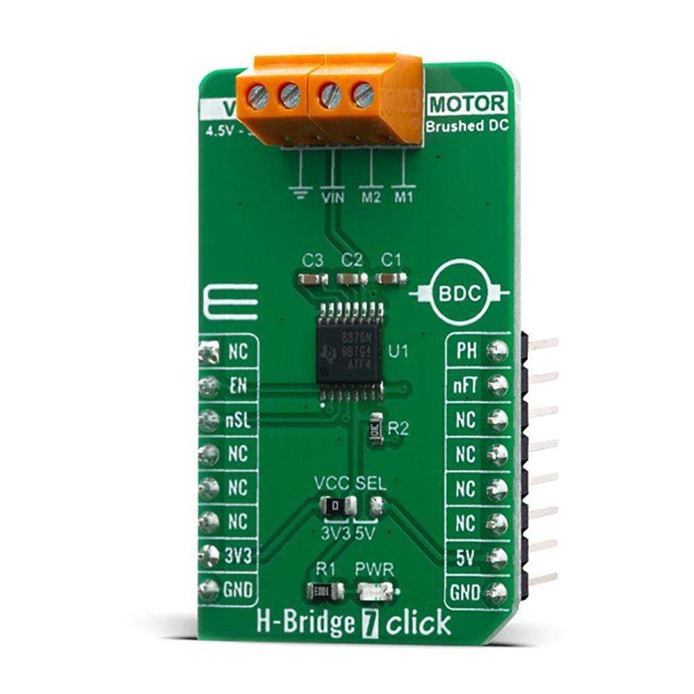
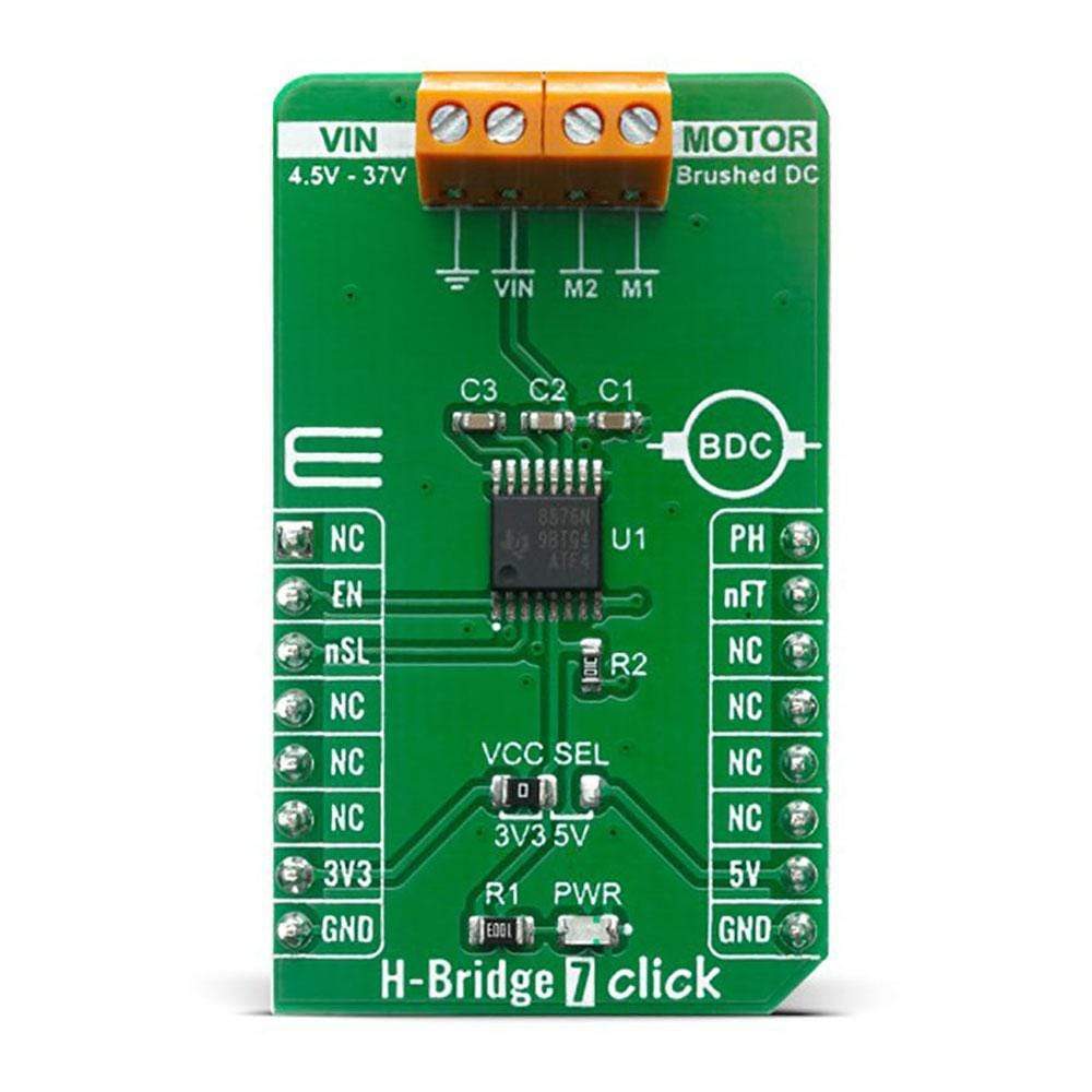
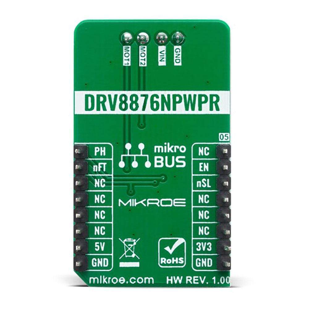
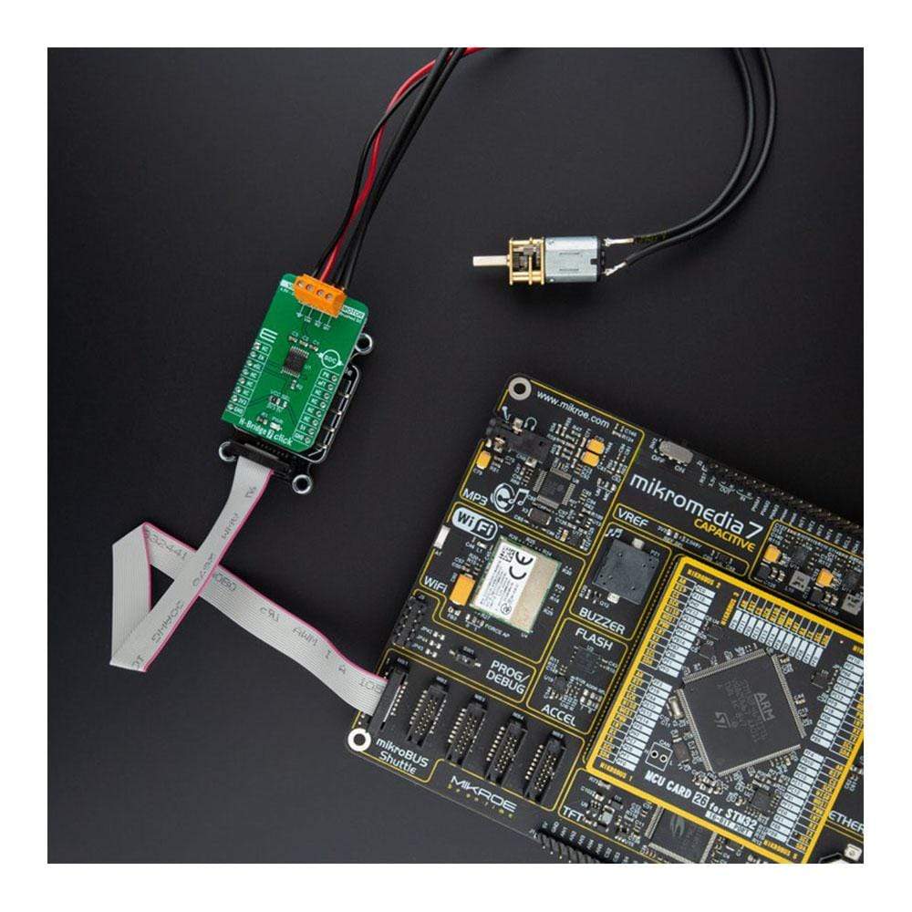
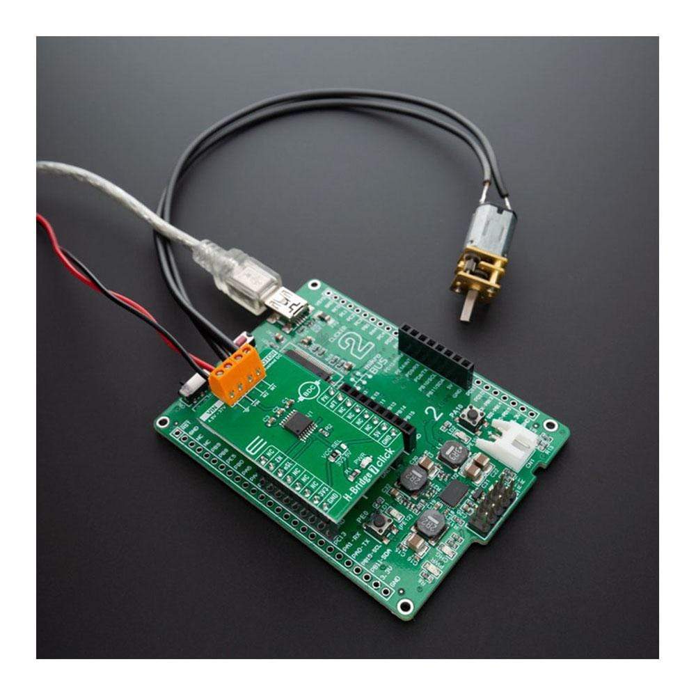
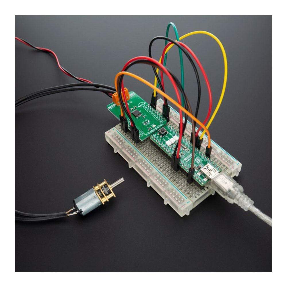
The H-Bridge 7 Click Board™ features flexible motor driver IC for a wide variety of applications, labelled as the DRV8876N. This Click Board™ integrates an N-channel H-bridge, charge pump regulator, and protection circuitry. The charge pump improves efficiency by allowing for both high-side and low-side N-channels MOSFETs and 100% duty cycle support.
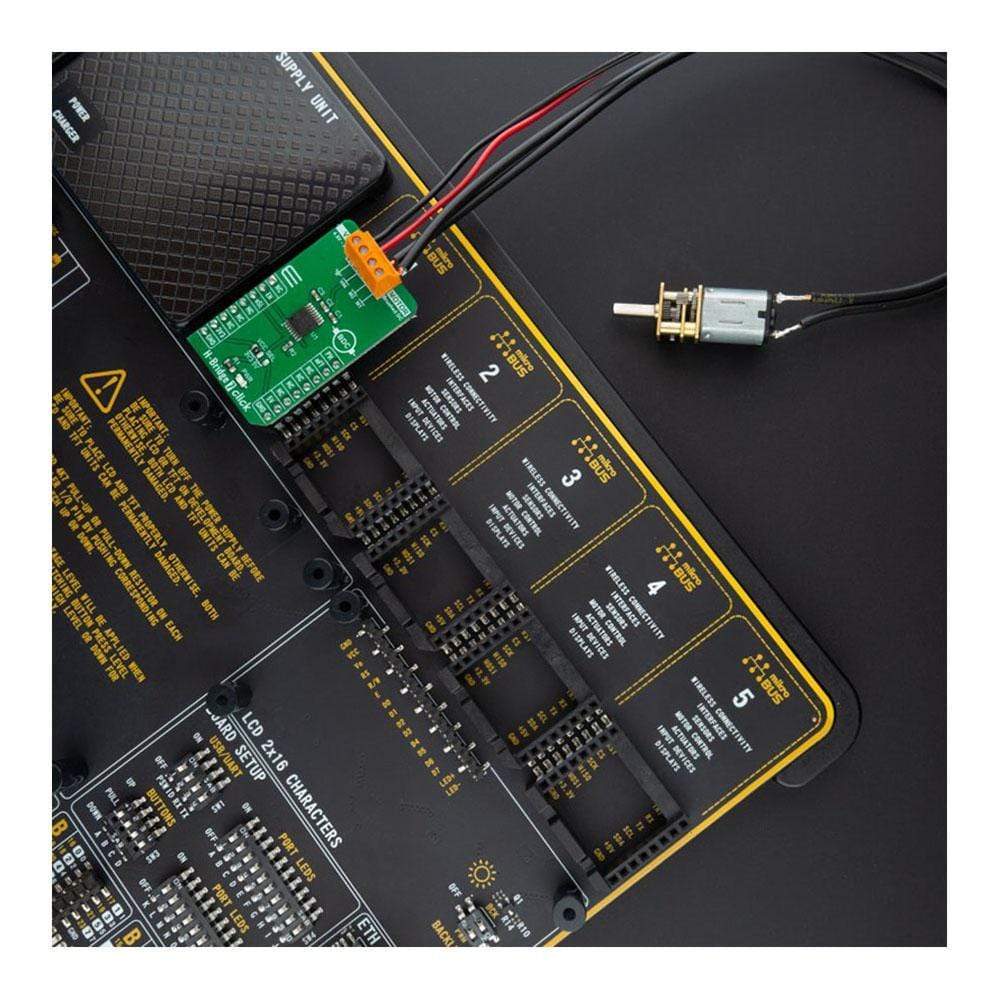
This IC allows the H-Bridge 7 Click Board™ to achieve ultra-low quiescent current draw by shutting down most of the internal circuitry with his low-power sleep mode. Internal protection features are provided for supply under-voltage lockout (UVLO), charge pump under-voltage (CPUV), output overcurrent (OCP), and device overtemperature (TSD). Fault conditions are indicated on the nFAULT pin (nFT pin on mikroBUS™). H-Bridge 7 Click Board™ can be used for DC Brush motor drive, servo motors, actuators, and more.
Downloads
Das H-Bridge 7 Click Board™ verfügt über einen flexiblen Motortreiber-IC für eine Vielzahl von Anwendungen, gekennzeichnet als DRV8876N. Dieses Click Board™ integriert eine N-Kanal-H-Brücke, einen Ladungspumpenregler und eine Schutzschaltung. Die Ladungspumpe verbessert die Effizienz, indem sie sowohl High-Side- als auch Low-Side-N-Kanal-MOSFETs und 100 % Tastverhältnisunterstützung ermöglicht.
Dieser IC ermöglicht dem H-Bridge 7 Click Board™ eine extrem niedrige Ruhestromaufnahme, indem es den Großteil der internen Schaltkreise mit seinem Energiesparmodus abschaltet. Interne Schutzfunktionen sind für die Abschaltung bei Unterspannung der Versorgung (UVLO), Unterspannung der Ladungspumpe (CPUV), Ausgangsüberstrom (OCP) und Geräteübertemperatur (TSD) vorgesehen. Fehlerzustände werden auf dem nFAULT-Pin (nFT-Pin auf mikroBUS™) angezeigt. H-Bridge 7 Click Board™ kann für DC-Bürstenmotorantriebe, Servomotoren, Aktuatoren und mehr verwendet werden.
| General Information | |
|---|---|
Part Number (SKU) |
MIKROE-4143
|
Manufacturer |
|
| Physical and Mechanical | |
Weight |
0.02 kg
|
| Other | |
EAN |
8606018717699
|
Frequently Asked Questions
Have a Question?
Be the first to ask a question about this.