XPRO-Adapter Click Board
Overview
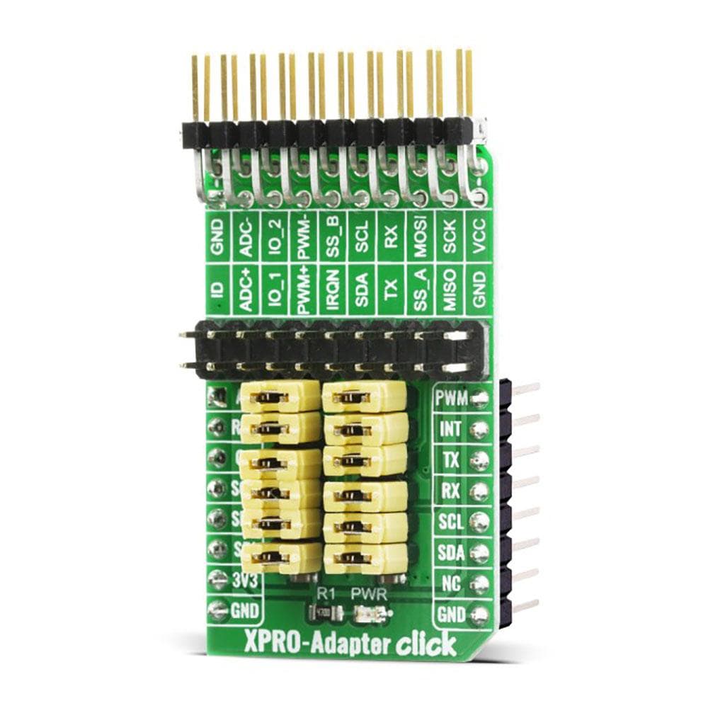
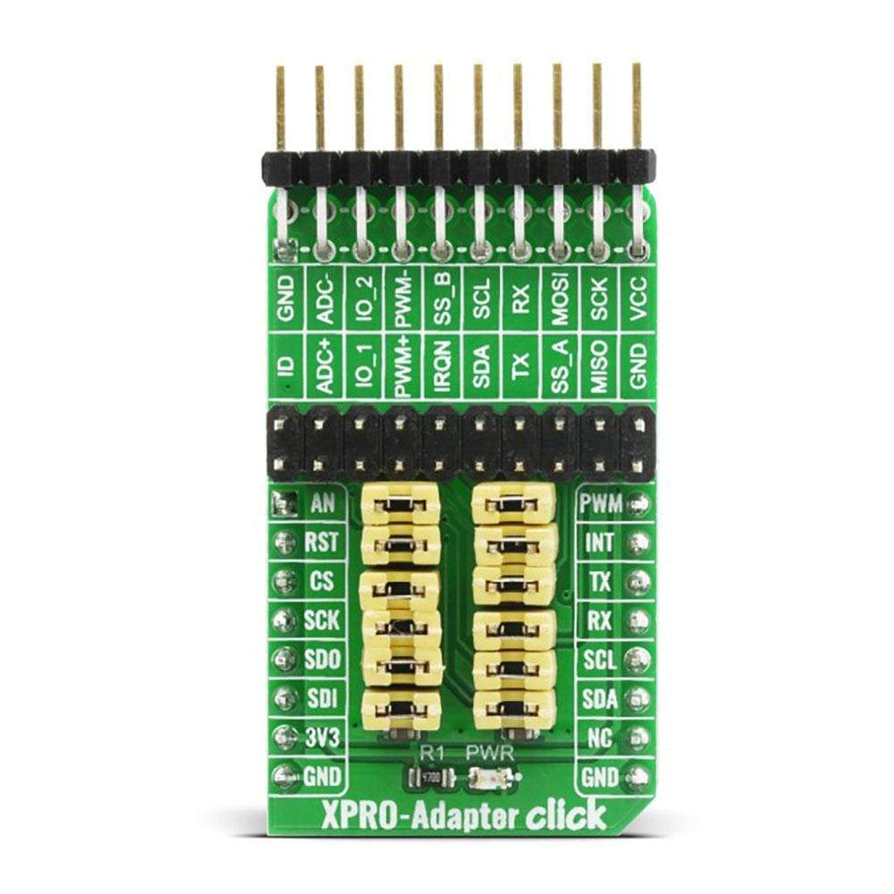
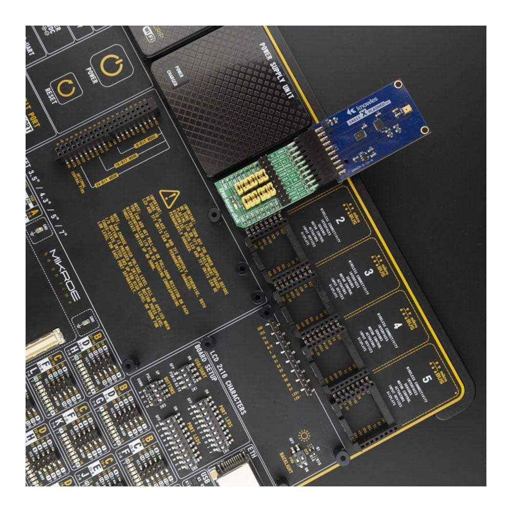
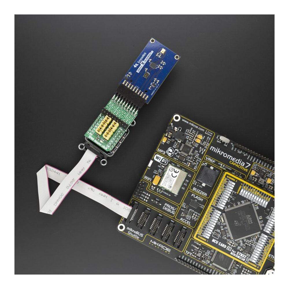
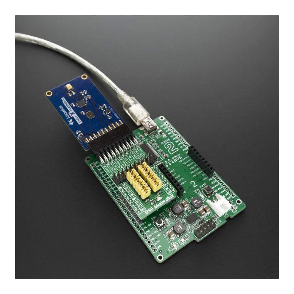
Das XPRO-Adapter Click Board™ ist eine Adapterplatine zum Verbinden von Microchip Xplaned Pro-Erweiterungsplatinen mit Hunderten von mikroBUS-basierten Hostplatinen. Der Xplaned Pro-Erweiterungs-Header ist ein standardisierter 20-poliger Steckverbinder, der den Anschluss vieler Microchip/ex Atmel-Erweiterungsplatinen ermöglicht. Dieses Click verfügt außerdem über duplizierte Xplaned Pro- und mikroBUS-Header, falls eine Neukonfiguration für einzelne Platinen oder Pinbelegungen erforderlich ist. Mit dem XPRO-Adapter Click können Sie jetzt Microchip-Zusatzplatinen auf mikroBUS ohne zusätzliche Verkabelung verwenden.
How Does The XPRO-Adapter Click Board™ Work?
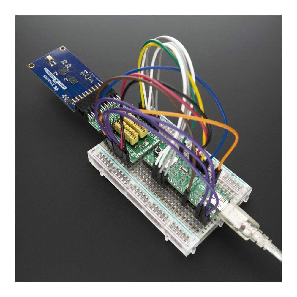
The XPRO-Adapter Click Board™ enables a mikroBUS™ 18-pin connector to interface with any Xplained Pro standard 20-pin extension boards from Microchip. Main goal of this boards is to provide interface between this two sockets at the same time offering the flexibility in reconfiguring I/O pinout between this two connectors. This is enabled on extended/duplicated headers so can customize pinout by removing jumpers and using wires to remap board default pinot.
All Xplained Pro boards have one or more dual row, 20-pin, 100mil female extension header. Note that all pins are not always connected. All connected pins follow the defined pin-out description in the table Below which you can find on the XPRO-Adapter Click silkscreen. As mentioned the extension headers can be used to connect a variety of Xplained Pro extensions to mirkoBUS MCU boards or to access the pins of the target MCU on Xplained Pro MCU boards directly.
This boards supports all standard communication interfaces which you may find on expansion boards such as SPI, I2C, UART, PWM (+/-), Analog (+/-). The ID pin which serves as communication line to the ID chip on an Xplaned Pro expansion boards is routed to the expanded mikroBUS connector and can be accessed and remapped if needed by using wire jumpers. The same goes for PWM lines which are available on the board however they need to be remapped to the appropriate mikroBUS pins before usage.
It is designed to be operated only with 3.3V logic levels. A proper logic voltage level conversion should be performed before the Click board™ is used with MCUs with logic levels of 5V.
SPECIFICATIONS
Type | Adapter |
Applications | The XPRO-Adapter Click Board™ connects Microchip Xplaned Pro expansion boards with hundreds of mikroBUS based host boards |
On-board modules | Xplained Pro boards have one or more dual row, 20-pin, 100mil female extension header |
Key Features | Support for many serial interfaces, 3.3V logic operation, remappable and configurable I/O's |
Interface | Analog,GPIO,I2C,PWM,SPI,UART |
Compatibility | mikroBUS |
Click board size | M (42.9 x 25.4 mm) |
Input Voltage | 3.3V |
PINOUT DIAGRAM
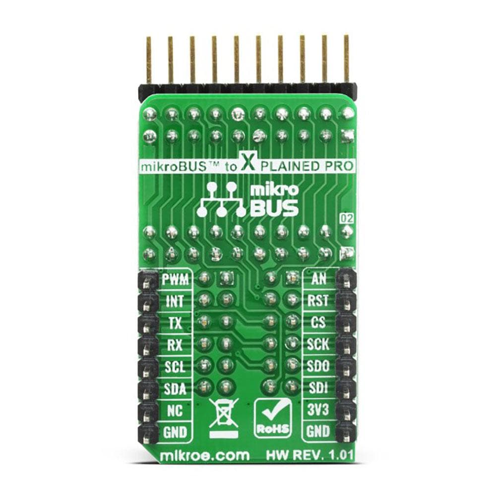
This table shows how the pinout of the XPRO-Adapter Click Board™ corresponds to the pinout on the mikroBUS™ socket (the latter shown in the two middle columns).
Notes | Pin | Pin | Notes | ||||
---|---|---|---|---|---|---|---|
Analog | AN | 1 | AN | PWM | 16 | PWM | External sync |
Reset | RST | 2 | RST | INT | 15 | INT | Interrupt |
SPI Chip Select | CS | 3 | CS | RX | 14 | TX | UART TX |
SPI Clock | SCK | 4 | SCK | TX | 13 | RX | UART RX |
SPI Data OUT | SDO | 5 | MISO | SCL | 12 | SCL | I2C Clock |
SPI Data IN | SDI | 6 | MOSI | SDA | 11 | SDA | I2C Data |
Power Supply | 3.3V | 7 | 3.3V | 5V | 10 | NC | |
Ground | GND | 8 | GND | GND | 9 | GND | Ground |
ONBOARD SETTINGS AND INDICATORS
Label | Name | Default | Description |
---|---|---|---|
LD1 | PWR | - | Power LED Indicator |
J2 | - | - | Xplained Pro Remap Header |
J3-4 | - | - | Extendend mikroBUS Remap Header |
Frequently Asked Questions
Have a Question?
Be the first to ask a question about this.