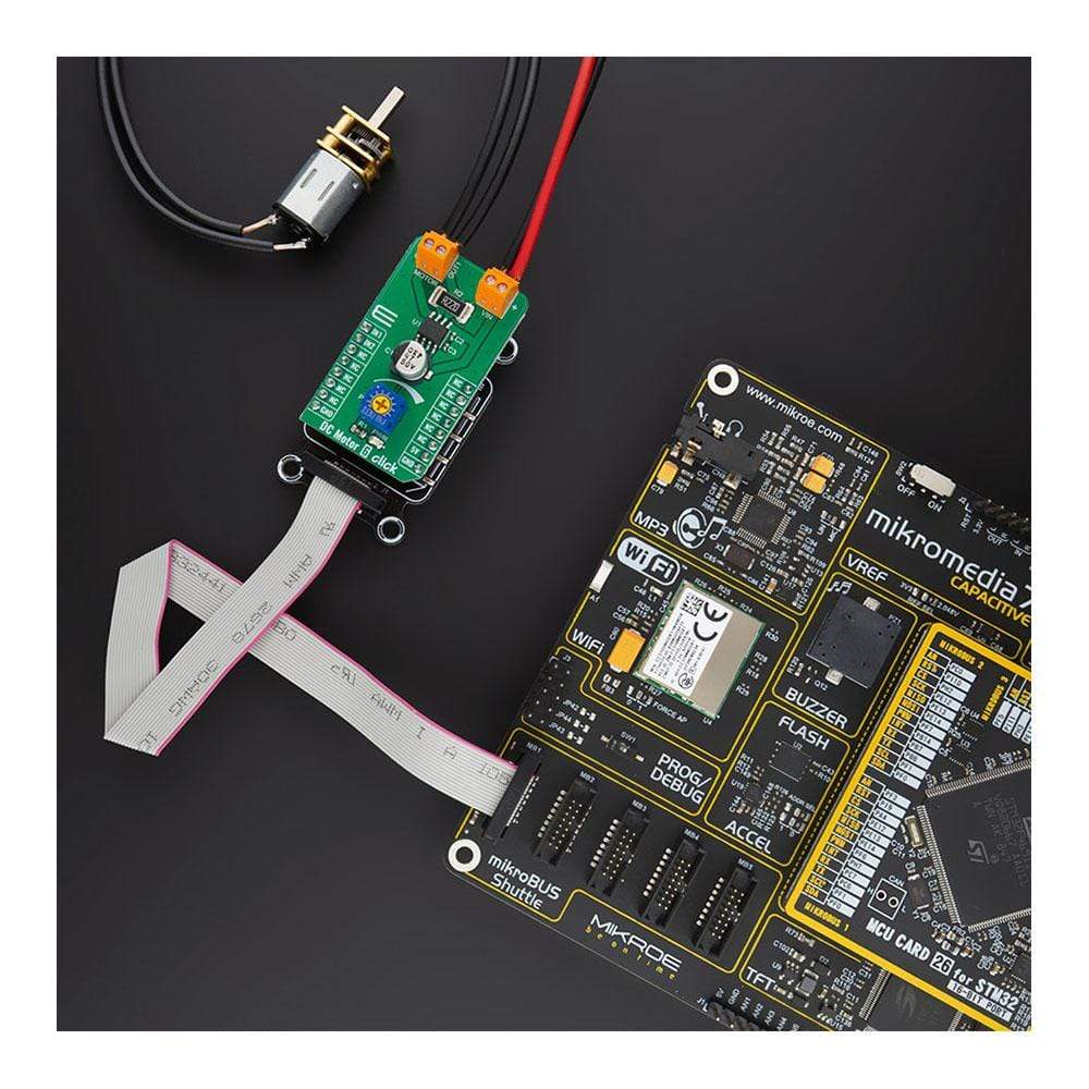
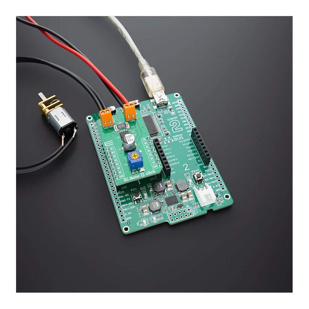
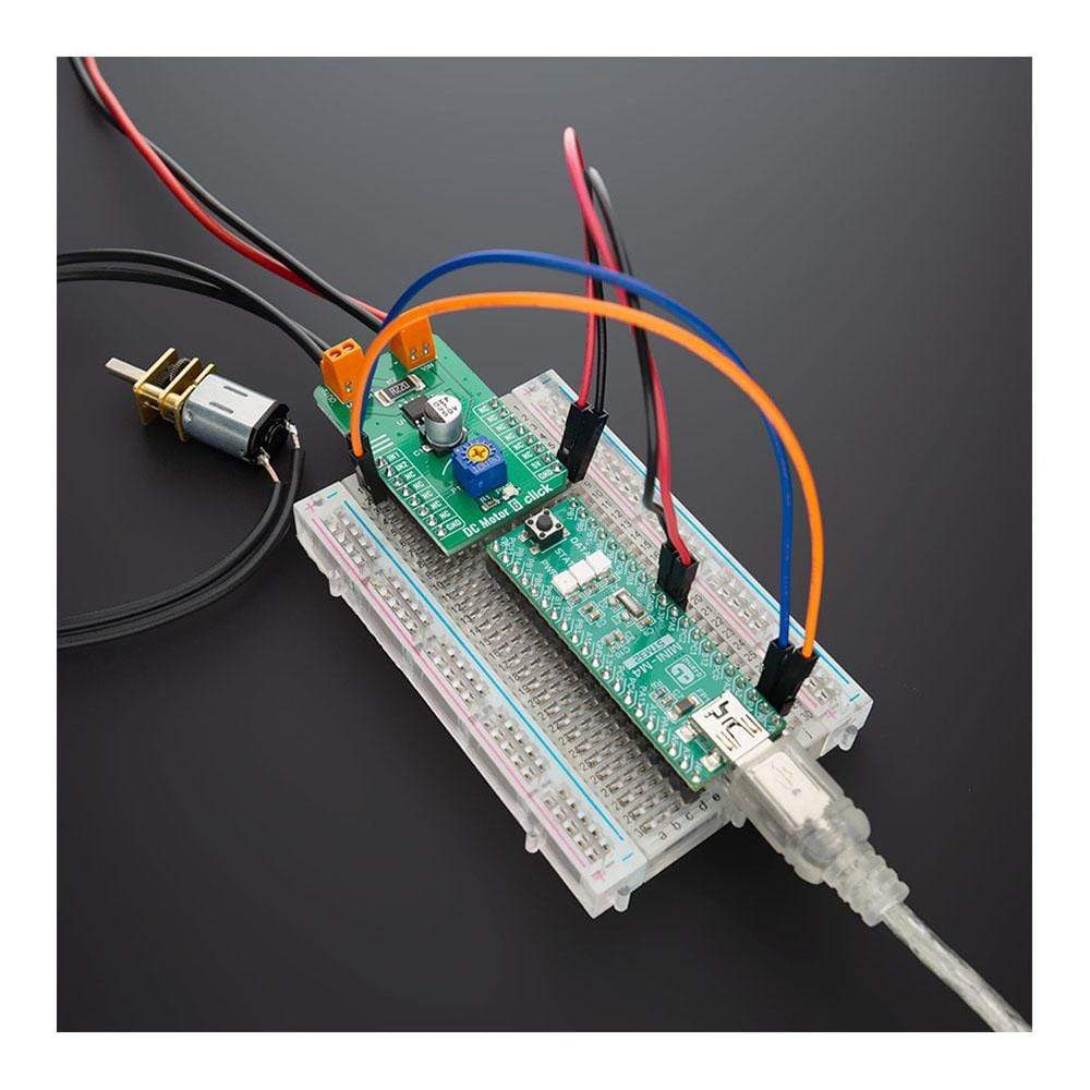
DC-Motor 6 Click-Platine
Overview
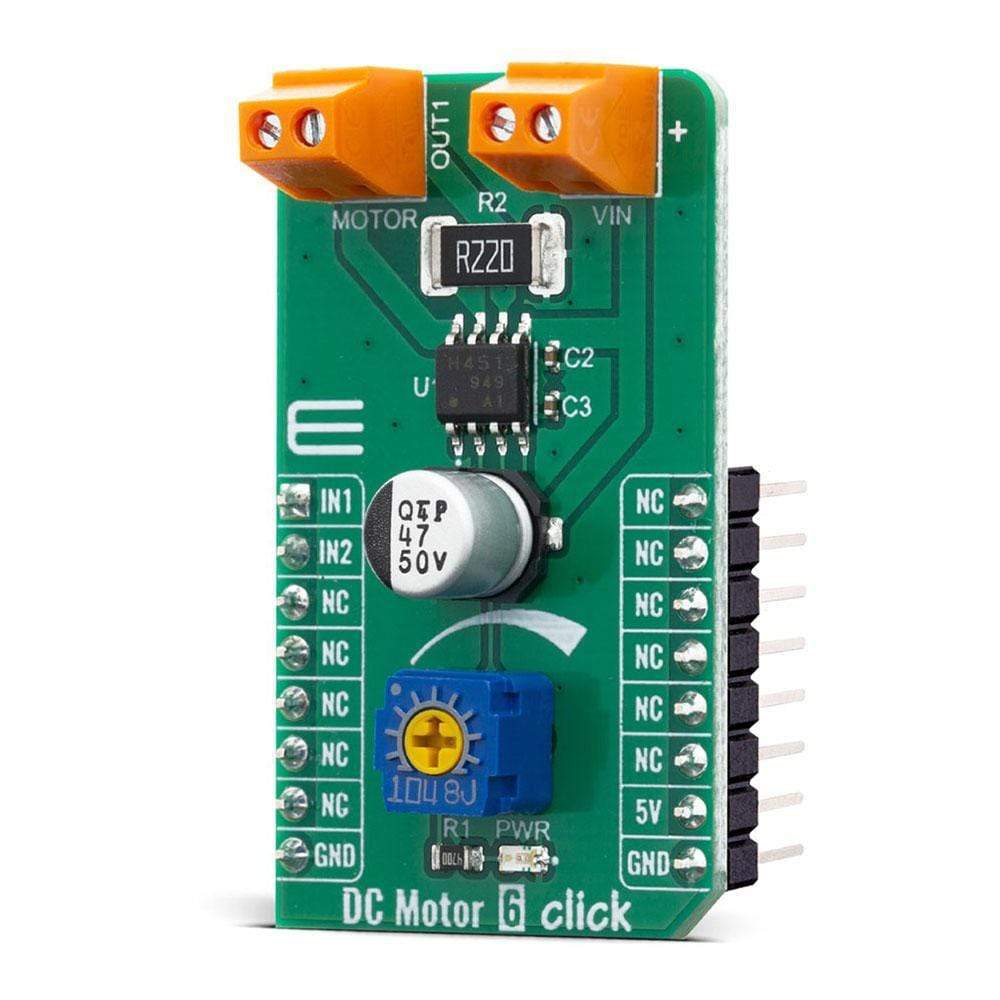
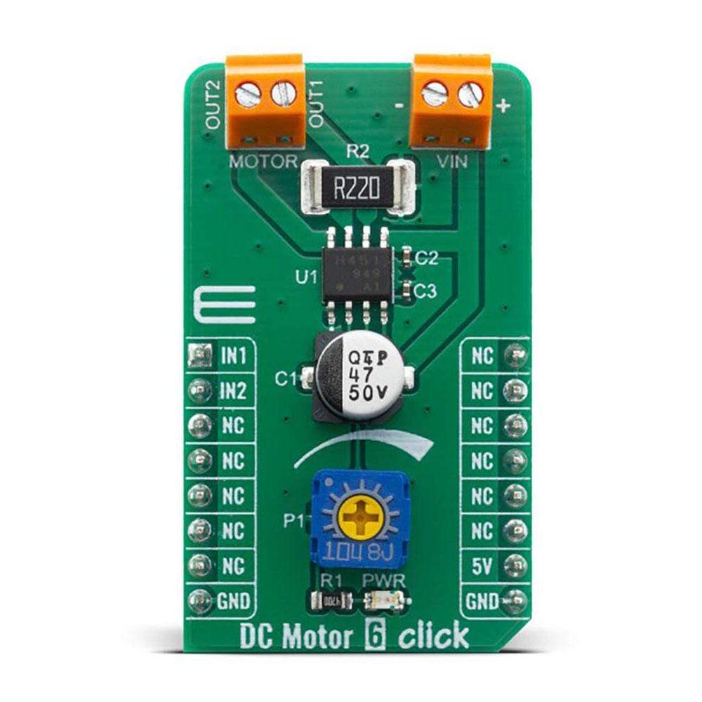
Das DC Motor 6 Click Board™ ist ein PWM-Chopper-Bürstenmotortreiber für Gleichstrommotoren mit der Bezeichnung TB67H451FNG. Dieser IC umfasst einen Kanal eines Motorausgangsblocks, der eine große Bandbreite an Versorgungsspannungen verwendet und gleichzeitig einen relativ hohen Strom an die angeschlossenen Gleichstrommotoren liefert. MOSFETs mit niedrigem Einschaltwiderstand und eine PWM-Steuerung tragen dazu bei, dass das TB67H451FNG eine geringere Wärmeentwicklung aufweist und somit einen effizienten Motorantrieb ermöglicht. Darüber hinaus verfügt das TB67H451FNG über zwei Eingänge, IN1 und IN2, die die Auswahl der vier Betriebsmodi ermöglichen: Vorwärts (im Uhrzeigersinn), Rückwärts (gegen den Uhrzeigersinn), kurze Pause und Stoppmodus.
Der DC Motor 6 Click wird von einer mikroSDK-kompatiblen Bibliothek unterstützt, die Funktionen enthält, die die Softwareentwicklung vereinfachen. Dieses Click Board™ wird als vollständig getestetes Produkt geliefert und ist bereit für den Einsatz auf einem System, das mit der mikroBUS™-Buchse ausgestattet ist.
How Does The DC Motor 6 Click Board™ Work?
The main component of the DC Motor 6 Click Board™ is the TB67H451FNG, a PWM chopper-type brushed DC motor driver, produced by Toshiba. This IC uses a proprietary BiCD manufacturing process, allowing this IC to be powered by a wide range of supply voltages, from 4.5 up to 44V. Due to a very low ON resistance of the MOSFETs, it can theoretically deliver up to 3A of current to the connected load. However, many external parameters affect both the maximum voltage and the current specifications, especially when the connected load is of a complex nature, such as the DC motor. In using TB67H451FNG, the voltage should be applied to the pins of VM and VREF. The absolute maximum rating of VM supply voltage is 50V (no active). The usage range is 4.5 to 44V. The absolute maximum rating of VREF supply voltage is 5V. The usage range is 0 to 4V.
There are no special procedures of inputting a power supply and shutdown because the TB67H451FNG incorporates the under voltage lockout (UVLO). However, under the unstable state of inputting the power supply (VM) and shutdown (transient area), setting the motor operation to OFF state is recommended. After the power supply is in the stable state, the motor should be operated by switching the input signal.The absolute maximum rating of motor output current is 3.5A. Its operating range is 3A or less. The maximum current of the actual usage is limited depending on the usage conditions (the ambient temperature, the wiring pattern of the board, the radiation path, and the exciting design). Configure the most appropriate current value after calculating the heat and evaluating the board under the operating environment.
This IC controls a motor operation by PWM constant current control. The peak current value (setting current value) can be determined by settings of the current-sensing resistor (R2) and the reference voltage (Vref). When both IN1 and IN2 pins are set to L for 1 ms (typ.) or more, the operation mode enters into the standby mode. When IN1 or IN2 is set to H, the mode returns from the standby mode, and enters to the operation mode.
The tBLK is intended to avoid inrush current detection. The TB67H451FNG not only can be controlled by constant current PWM, but also by direct PWM; with IN control signals.
When the supply voltage to VM pin is 3.8V or less, the internal circuit is triggered; the internal reset circuit then turns off the output transistors. Once the UVLO is triggered, it can be cleared by reasserting the VM supply voltage to 4.0V or more (typ.)
SPECIFICATIONS
Type | Brushed |
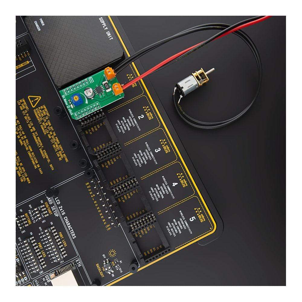
Applications | The DC Motor 6 Click Board™ is suitable for RC cars and boats, small to medium-sized robots, drones, and similar applications. as well as for driving motors in air or water pumps, air conditioners, ventilation systems, handheld tools, etc. |
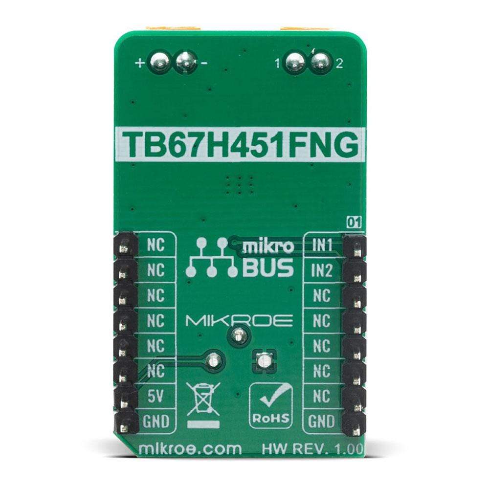
On-board modules | TB67H451FNG |
Key Features | The DC Motor 6 Click Board™ is a PWM chopper type brushed DC motor driver, labeled as TB67H451FNG. This IC includes one channel of motor output block, using a wide range of supply voltages, while delivering reasonably high current to the connected DC motors. |
Interface | GPIO |
Compatibility | mikroBUS |
Click board size | M (42.9 x 25.4 mm) |
Input Voltage | 5V |
PINOUT DIAGRAM
This table shows how the pinout of the DC Motor 6 Click Board™ corresponds to the pinout on the mikroBUS™ socket (the latter shown in the two middle columns).
Notes | Pin | Pin | Notes | ||||
---|---|---|---|---|---|---|---|
Ctrl IN 1 | IN1 | 1 | AN | PWM | 16 | NC | |
Ctrl IN 2 | IN2 | 2 | RST | INT | 15 | NC | |
NC | 3 | CS | RX | 14 | NC | ||
NC | 4 | SCK | TX | 13 | NC | ||
NC | 5 | MISO | SCL | 12 | NC | ||
NC | 6 | MOSI | SDA | 11 | NC | ||
NC | 7 | 3.3V | 5V | 10 | 5V | Power Supply | |
Ground | GND | 8 | GND | GND | 9 | GND | Ground |
ONBOARD SETTINGS AND INDICATORS
Label | Name | Default | Description |
---|---|---|---|
PWR | LED GREEN | - | Power LED Indicator |
P1 | P1 | - | Reference voltage trimmer |
DC MOTOR 6 CLICK ELECTRICAL SPECIFICATIONS
Description | Min | Typ | Max | Unit |
---|---|---|---|---|
VM Power Supply | 4.5 | 24 | 44 | V |
Motor output current | 0 | 1.5 | 2 | A |
Input range of Vref voltage | 0 | 2 | 4 | V |
Operating temperature range | -40 | - | 85 | °C |
Logic input (VIN(L)) | 0 | - | 0.8 | V |
Logic input (VIN(H)) | 2 | - | 5.5 | V |
We provide a library for the DC Motor 6 Click Board™ on our LibStock page, as well as a demo application (example), developed using MikroElektronika compilers. The demo can run on all the main MikroElektronika development boards.
Library Description
The library contains functions for working with the DC Motor 6 Click Board™.
Key Functions
void dcmotor6_set_direction( uint8_t dir )
- Set motor direction
Example Description
The application is composed of three sections :
- System Initialization - Initializes all necessary gpio pins
- Application Initialization - Initializes driver init
- Application Task - Set the motor direction in clockwise and Counter-clockwise direction.
void application_task ( ) { dcmotor6_set_direction( DCMOTOR6_MOTOR_DIR_CCW ); Delay_ms( 2000 ); dcmotor6_set_direction( DCMOTOR6_MOTOR_STOP ); Delay_ms( 2000 ); dcmotor6_set_direction( DCMOTOR6_MOTOR_DIR_CW ); Delay_ms( 2000 ); dcmotor6_set_direction( DCMOTOR6_MOTOR_STOP ); Delay_ms( 2000 ); }
The full application code, and ready to use projects can be found on our LibStock page.
Other mikroE Libraries used in the example:
- GPIO
Additional Notes and Information
Depending on the development board you are using, you may need a USB UART click, USB UART 2 click or RS232 click to connect to your PC, for development systems with no UART to USB interface available on the board. The terminal available in all MikroElektronika compilers, or any other terminal application of your choice, can be used to read the message.
MIKROSDK
The DC Motor 6 Click Board™ is supported with mikroSDK - MikroElektronika Software Development Kit. To ensure proper operation of mikroSDK compliant Click board™ demo applications, mikroSDK should be downloaded from the LibStock and installed for the compiler you are using.
Frequently Asked Questions
Have a Question?
Be the first to ask a question about this.