Audio XOver Click-Platine
Overview
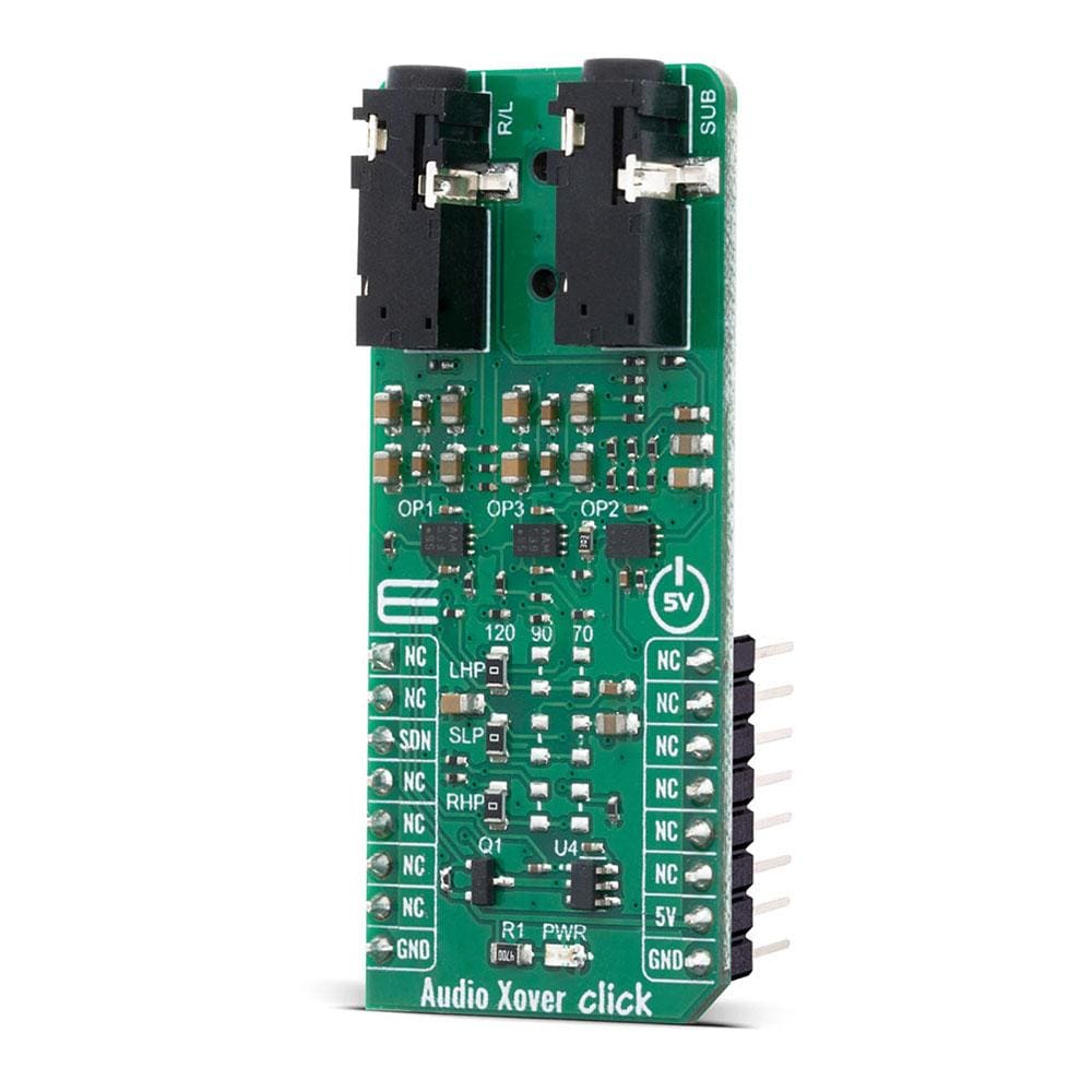
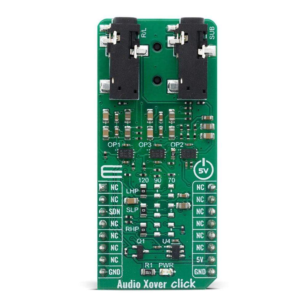
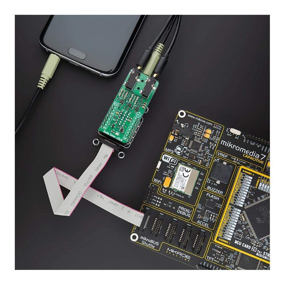
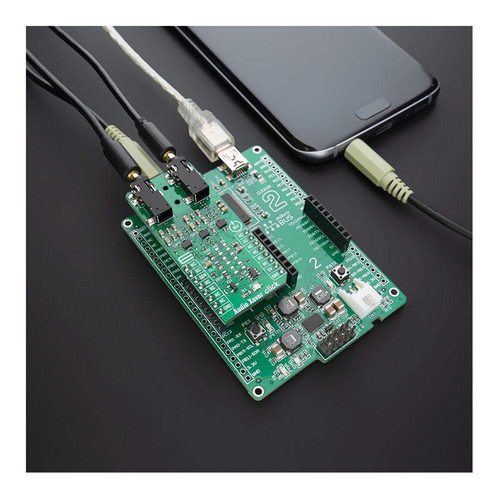
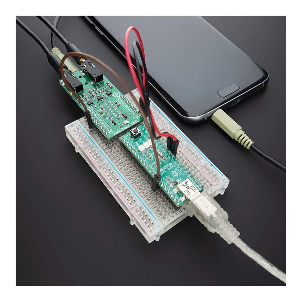
Der Audio-Weiche Click Board™ ist eine analoge aktive Crossover-Lösung für Zweiwegelautsprecher. Der Hauptzweck der Crossover-Schaltung in einem Lautsprecher besteht darin, ein eingehendes Audiosignal in Frequenzbänder aufzuteilen, die an den am besten geeigneten Lautsprecher oder „Treiber“ weitergeleitet werden. Audio Xover Click basiert auf dem Operationsverstärker MCP6H012 von Microchip mit Rail-to-Rail-Ausgangsbetrieb, der in einer Konfiguration für Butterworth-Filter 2. Ordnung für Tiefpass- und Hochpassfilter angeschlossen ist. Mit einem Frequenzgang, der unabhängig von den dynamischen Änderungen der elektrischen Eigenschaften eines Treibers ist, und der Auswahl der Grenzfrequenz einzelner Kanäle ist es eine hervorragende Lösung für Crossover.
Das Audio Xover Click Board™ wird durch eine mikroSDK-kompatible Bibliothek unterstützt, die Funktionen enthält, die die Softwareentwicklung vereinfachen. Dieses Click Board™ ist ein gründlich getestetes Produkt und kann auf einem System verwendet werden, das mit der mikroBUS™-Buchse ausgestattet ist.
How Does The Audio Xover Click Board™ Work
The Audio Xover Click Board™ uses three Butterworth filters (one for each speaker) with possibility of changing cutoff frequency between 120Hz, 90Hz and 70Hz. Butterworth filters are called maximally flat filters because, for a given order, they have the sharpest roll-off possible without inducing peaking in the Bode plot. The two-pole filter with a damping ratio of 0.707 is the second-order Butterworth filter.
Audio crossovers are a type of electronic filter circuitry used in a range of audio applications, to split up an audio signal into two or more frequency ranges, so that the signals can be sent to drivers that are designed for different frequency ranges.
Active crossovers are distinguished from passive crossovers in that whereas passive crossovers split up an amplified signal coming from one power amplifier so that it can be sent to two or more drivers (e.g., a woofer and a very low frequency subwoofer, or a woofer and a tweeter), an active crossover splits up audio signal prior to amplification, so that it can be sent to two or more power amplifiers, each of which is connected to a separate driver type.
Active crossovers as Audio Xover Click don't care how powerful your amplifiers are because they process the signal before it enters the amplifier. Active crossovers are also not very sensitive to temperature variations, so they can be very accurate, all the time. If one of the amplifiers channels in an active crossover system clips, the distortion only affects that single channel.
SPECIFICATIONS
Type | Signal Processing |
Applications | Audio crossover |
On-board modules | MCP6H012 |
Key Features | A frequency response independent of the dynamic changes in a driver's electrical characteristics, power amplifiers are directly connected to the speaker drivers, individual channel cutoff frequency selection... |
Interface | GPIO |
Compatibility | mikroBUS |
Click board size | L (57.15 x 25.4 mm) |
Input Voltage | 5V |
PINOUT DIAGRAM
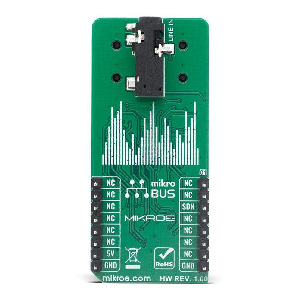
This table shows how the pinout on Audio Xover Click corresponds to the pinout on the mikroBUS™ socket (the latter shown in the two middle columns).
Notes | Pin | Pin | Notes | ||||
---|---|---|---|---|---|---|---|
NC | 1 | AN | PWM | 16 | NC | ||
NC | 2 | RST | INT | 15 | NC | ||
Shutdown | SDN | 3 | CS | RX | 14 | NC | |
NC | 4 | SCK | TX | 13 | NC | ||
NC | 5 | MISO | SCL | 12 | NC | ||
NC | 6 | MOSI | SDA | 11 | NC | ||
NC | 7 | 3.3V | 5V | 10 | 5V | Power Supply | |
Ground | GND | 8 | GND | GND | 9 | GND | Ground |
ONBOARD SETTINGS AND INDICATORS
Label | Name | Default | Description |
---|---|---|---|
PWR | LED GREEN | - | Power LED Indicator |
LHP | SL1 | Left | Left channel high pass cutoff frequency selector; Left: 120Hz |
SLP | SW1 | Left | Subwoofer channel low pass cutoff frequency selector; Middle: 90Hz |
RHP | SR1 | Left | Right channel high pass cutoff frequency selector; Right: 70Hz |
Software Support
We provide a library for the Audio Xover Click on our LibStock page, as well as a demo application (example), developed using MikroElektronika compilers. The demo can run on all the main MikroElektronika development boards.
Library Description
Library contains function for enable and disable module.
Key Functions
void audioxover_set_mode( uint8_t state )
- This function set CS pin on 1 ( ENABLE ) and 0 ( DISABLE )
Example Description
The application is composed of three sections :
- System Initialization - Initializes all necessary GPIO pins
- Application Initialization - Initializes driver init
- Application Task - Enable and disable module every one seconds.
void application_task ( ) { mikrobus_logWrite( "***ENABLE****", _LOG_LINE ); audioxover_set_mode( AUDIOXOVER_ENABLE ); Delay_ms( 3000 ); mikrobus_logWrite( "***DISABLE****", _LOG_LINE ); audioxover_set_mode( AUDIOXOVER_DISABLE ); Delay_ms( 3000 ); }
The full application code, and ready to use projects can be found on our LibStock page.
Other mikroE Libraries used in the example:
- LOG(UART) Library
Additional Notes and Information
Depending on the development board you are using, you may need USB UART click, USB UART 2 click or RS232 click to connect to your PC, for development systems with no UART to USB interface available on the board. The terminal available in all MikroElektronika compilers, or any other terminal application of your choice, can be used to read the message.
MIKROSDK
This Click board™ is supported with mikroSDK - MikroElektronika Software Development Kit. To ensure proper operation of mikroSDK compliant Click board™ demo applications, mikroSDK should be downloaded from the LibStock and installed for the compiler you are using.
Frequently Asked Questions
Have a Question?
Be the first to ask a question about this.