


Mikroelektronika d.o.o.
ISO ADC Click-Platine
ISO ADC Click-Platine
SKU: MIKROE-4088
Verfügbarkeit für Abholungen konnte nicht geladen werden


Overview
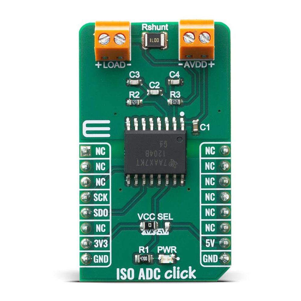
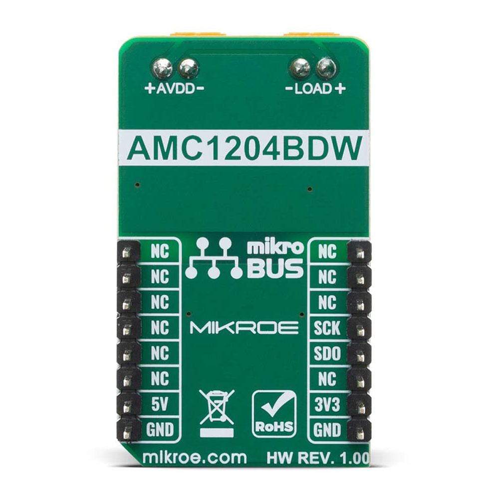
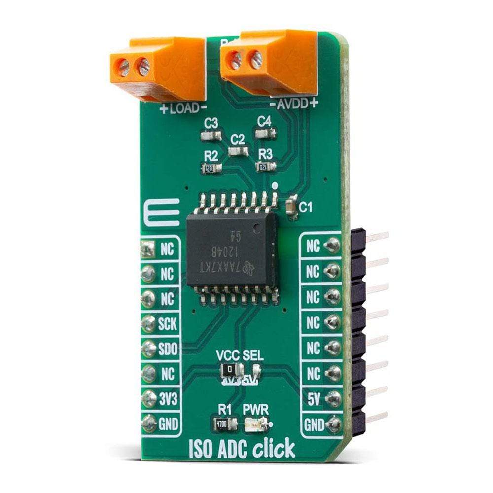
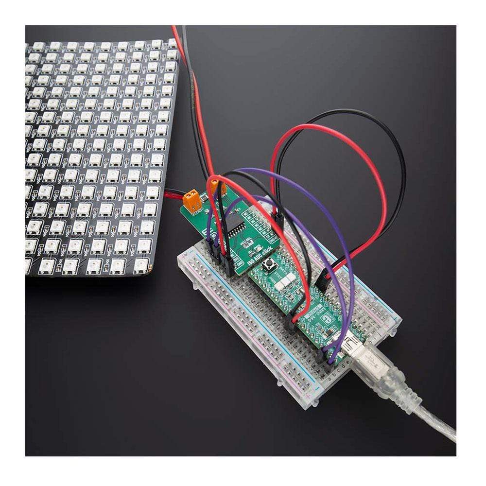
The ISO ADC Click Board™ is add-on board current-shunt measurement device with isolated delta-sigma modulator. This Click Board™ is based on AMC1204BDWR provide a single-chip solution for measuring the small signal of a shunt resistor across an isolated barrier from Texas Instruments. ISO ADC Click contains shunt resistor, these types of resistors are typically used to sense currents in motor control inverters, green energy generation systems, and other industrial applications.
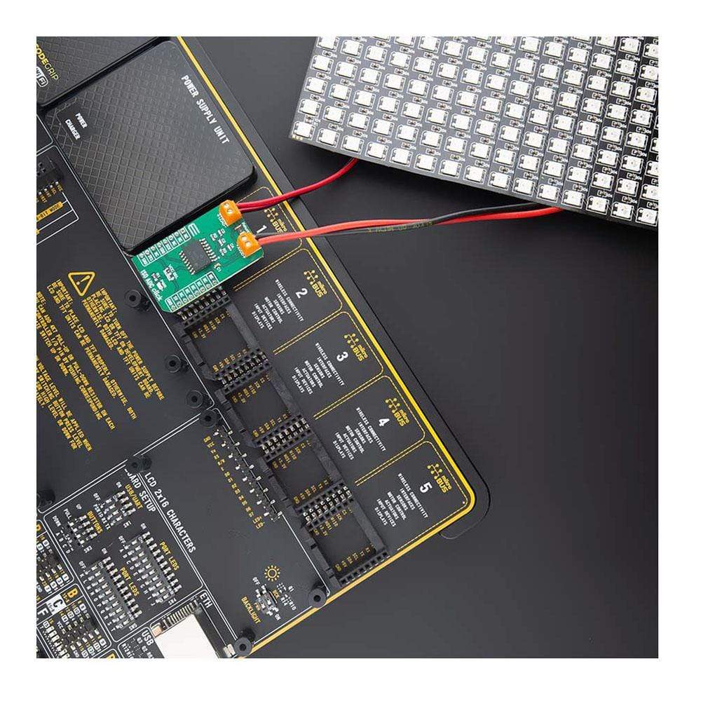
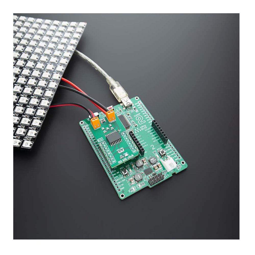
The ISO ADC Click Board™ is supported by a mikroSDK compliant library, which includes functions that simplify software development. This Click Board™ comes as a fully tested product, ready to be used on a system equipped with the mikroBUS™ socket.
Downloads
Das ISO ADC Click Board™ ist ein Zusatzplatinen-Strom-Shunt-Messgerät mit isoliertem Delta-Sigma-Modulator. Dieses Click Board™ basiert auf AMC1204BDWR und bietet eine Single-Chip-Lösung zum Messen des Kleinsignals eines Shunt-Widerstands über eine isolierte Barriere von Texas Instruments. ISO ADC Click enthält Shunt-Widerstände. Diese Widerstandstypen werden typischerweise zum Erfassen von Strömen in Motorsteuerungswechselrichtern, grünen Energieerzeugungssystemen und anderen industriellen Anwendungen verwendet.
Das ISO ADC Click Board™ wird von einer mikroSDK-kompatiblen Bibliothek unterstützt, die Funktionen enthält, die die Softwareentwicklung vereinfachen. Dieses Click Board™ wird als vollständig getestetes Produkt geliefert und ist bereit für den Einsatz auf einem System, das mit der mikroBUS™-Buchse ausgestattet ist.
| General Information | |
|---|---|
Part Number (SKU) |
MIKROE-4088
|
Manufacturer |
|
| Physical and Mechanical | |
Weight |
0.023 kg
|
| Other | |
EAN |
8606018717309
|
Frequently Asked Questions
Have a Question?
Be the first to ask a question about this.