Zu Produktinformationen springen
1 von 7

Mikroelektronika d.o.o.

AN-zu-PWM-Click-Platine

AN-zu-PWM-Click-Platine

SKU: MIKROE-4060
Normaler Preis
£9.80 GBP ohne MwSt
Normaler Preis £14.00 GBP Verkaufspreis
£9.80 GBP ohne MwSt
Sale Ausverkauft
Versand wird beim Checkout berechnet
If no stock shown above, check availability
Vollständige Details anzeigen
} ] }

Overview

Das AN-zu-PWM-Click-Board™ ist ein Gerät, das den Wert des analogen Eingangssignals mit praktisch jeder Wellenform in eine PWM-Spannungsausgabe mit fester Frequenz umwandelt, mit einem Arbeitszyklus proportional zur Eingangsspannung. Es hat eine lineare Reaktion und durch Anlegen eines Signals mit einer Spannung zwischen -2,5 V und +2,5 V an seinem Eingang erzeugt das Click-Board™ eine pulsweitenmodulierte (PWM) Ausgangsspannung mit einem Arbeitszyklus von 0 % bis 100 %.

Das AN-zu-PWM-Click-Modul zeichnet sich durch eine sehr gute Linearität aus, deckt einen positiven und negativen Eingangsspannungsbereich ab und weist eine gute Temperaturstabilität auf. Dank dieser Funktionen kann dieses Gerät in verschiedenen Spannungs-Frequenz-Anwendungen eingesetzt werden, z. B. in AD-Umwandlungs-, Inspektions-, Test- und Messgeräten. Es kann auch als variabler Taktsignalgenerator verwendet werden.

How Does The AN to PWM Click Board™ Work?

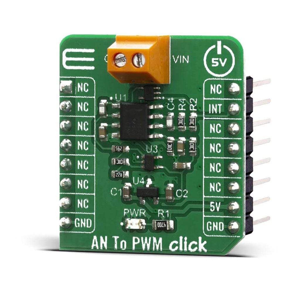
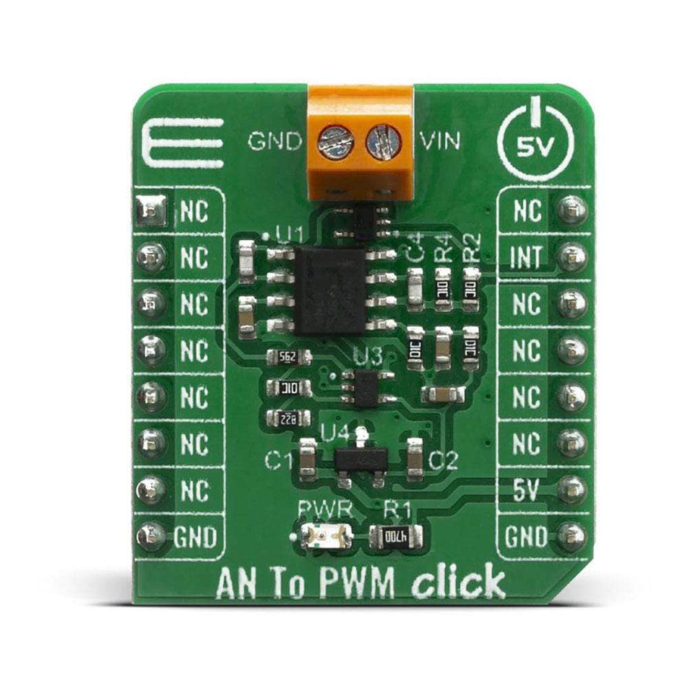
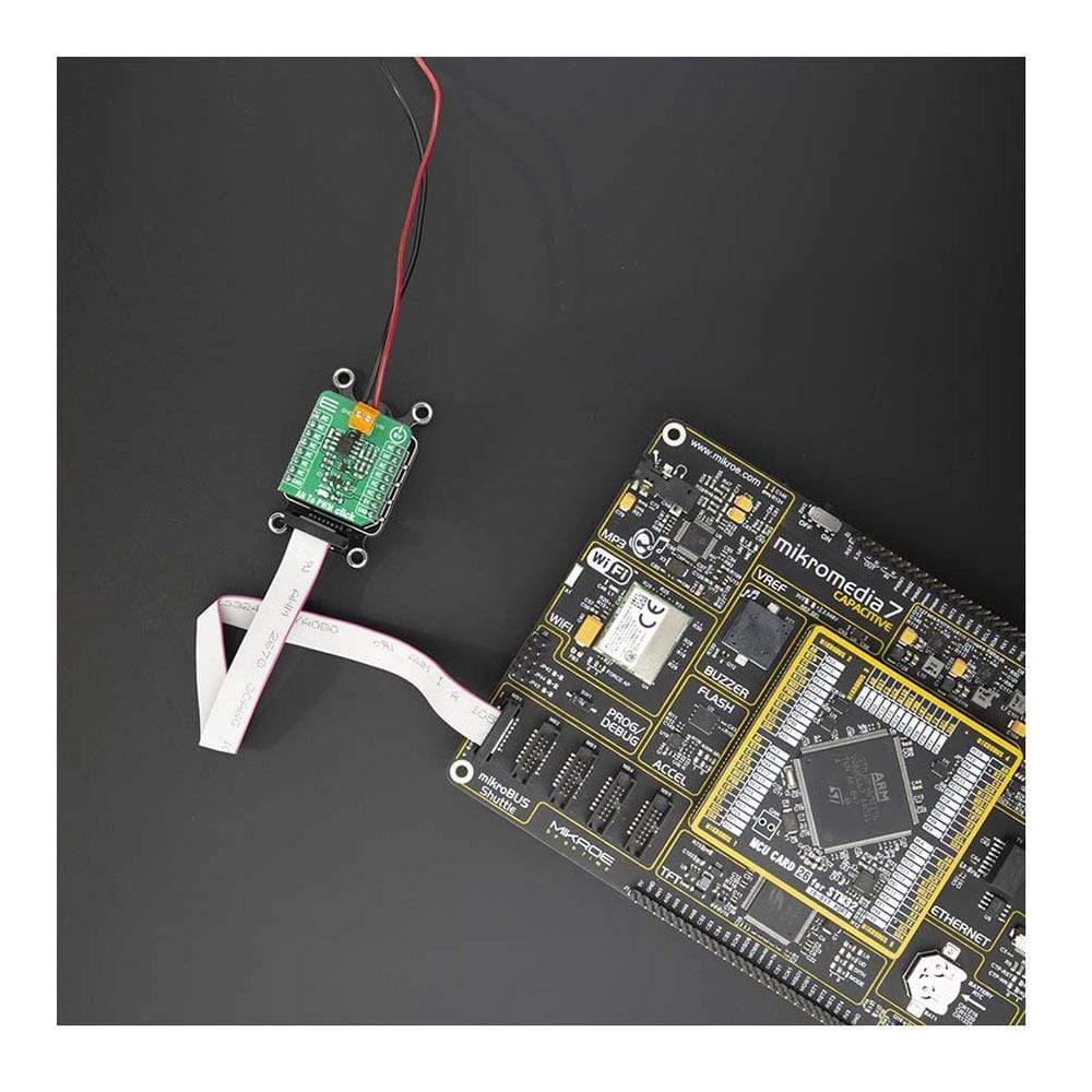
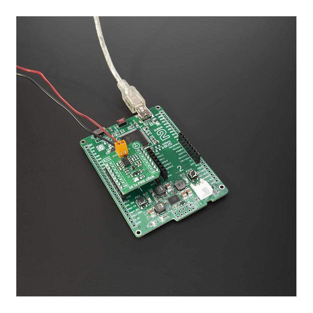
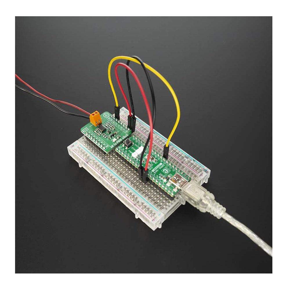
The AN to PWM Click Board™ is a device that converts an analog voltage input signal into a pulse width modulated (PWM) output signal. This Click Board™ consists of an analog circuitry, made of two comparators and two op-amps, needed for the described device. Op-amps used on this Click Board™ are OPA365 series, while comparators used are TLV 3201, both from Texas Instruments. It has a linear response, so applying a voltage in a range of -2.5 to 2.5V on its input, will result in generating the PWM pulse train with duty cycle linearly proportional to the input voltage.

AN to PWM Click Board™

This circuit on this Click Board™ utilizes a triangle wave generator and comparator to generate a pulse-width-modulated (PWM) waveform with a duty cycle that is inversely proportional to the input voltage. An op amp and comparator generate a triangular waveform which is passed to the inverting input of a second comparator. By passing the input voltage to the non-inverting comparator input, a PWM waveform is produced. Negative feedback of the PWM waveform to an error amplifier is utilized to ensure high accuracy and linearity of the output.

One op-amp (U1a) and one comparator (U3) are used in order to form the triangle wave generator. The error amplifier, composed of one op-amp U1b, serves two purposes. First, the error amplifier accommodates feedback of the output PWM waveform in order to correct for any errors in the output voltage introduced by the comparator on the output of the circuit (U2). Second, it adds a dc offset to the input voltage so that negative input voltages can be accommodated by the circuit. That way, in case that input signal is equal to 0V, the value of PWM duty cycle on the output is 50%.

The output PWM signal on the AN to PWM Click Board™ is brought to the INT pin of the mikroBUS socket, in order to enable fast and precise duty cycle measurement, using the interrupt routines. The frequency of the PWM signal is fixed to 500kHz.

The AN to PWM Click Board™ is designed to be operated only with 5V logic level. A proper logic voltage level conversion should be performed before the Click Board™ is used with MCUs with logic levels of 3.3V.

SPECIFICATIONS

Type Measurements
Applications AD conversion, inspection, test and measurement equipment, while it can also be used as the variable clock signal generator.
On-board modules OPA2365 – Dual 50MHz, Low-Noise, Single-Supply Rail-to-Rail Operational Amplifier; TLV3201 - 40-ns, microPOWER, push-pull output comparator, both from Texas Instruments.
Key Features Very good linearity, covers a positive and negative input voltage range and it has good temperature stability
Interface GPIO
Compatibility mikroBUS
Click Board™ size S (28.6 x 25.4 mm)
Input Voltage 5V

Pinout Diagram

This table shows how the pinout on the AN to PWM Click Board™ corresponds to the pinout on the mikroBUS socket (the latter shown in the two middle columns).

Notes Pin mikroBUS logo.png Pin Notes
  NC 1 AN PWM 16 NC  
  NC 2 RST INT 15 INT PWM Output
  NC 3 CS RX 14 NC  
  NC 4 SCK TX 13 NC  
  NC 5 MISO SCL 12 NC  
  NC 6 MOSI SDA 11 NC  
  NC 7 3.3V 5V 10 5V Power Suppluy
Ground GND 8 GND GND 9 GND Ground


ONBOARD SETTINGS AND INDICATORS

Label Name Default  Description
LD1 PWR - Power LED Indicator


Frequently Asked Questions

Have a Question?

Be the first to ask a question about this.

Ask a Question

Customer Reviews

Be the first to write a review
0%
(0)
0%
(0)
0%
(0)
0%
(0)
0%
(0)