


Mikroelektronika d.o.o.
Monarch Adapter Click-Platine
Monarch Adapter Click-Platine
SKU: MIKROE-4057
Verfügbarkeit für Abholungen konnte nicht geladen werden

Overview
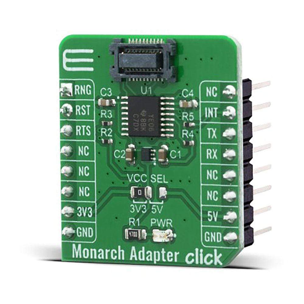
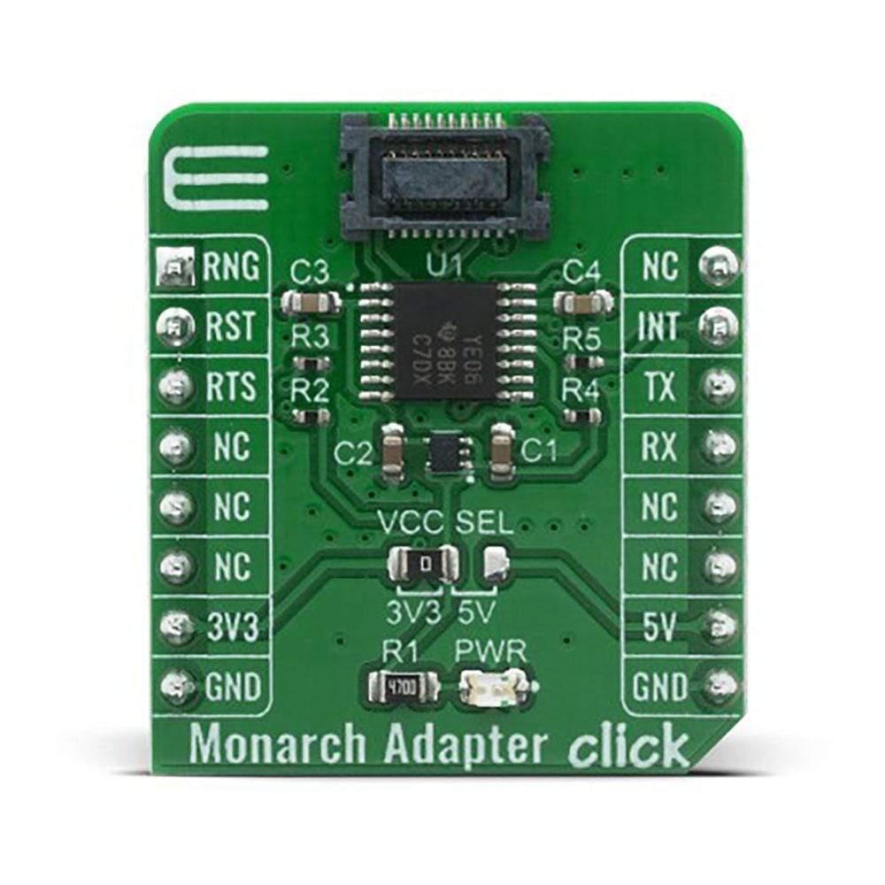
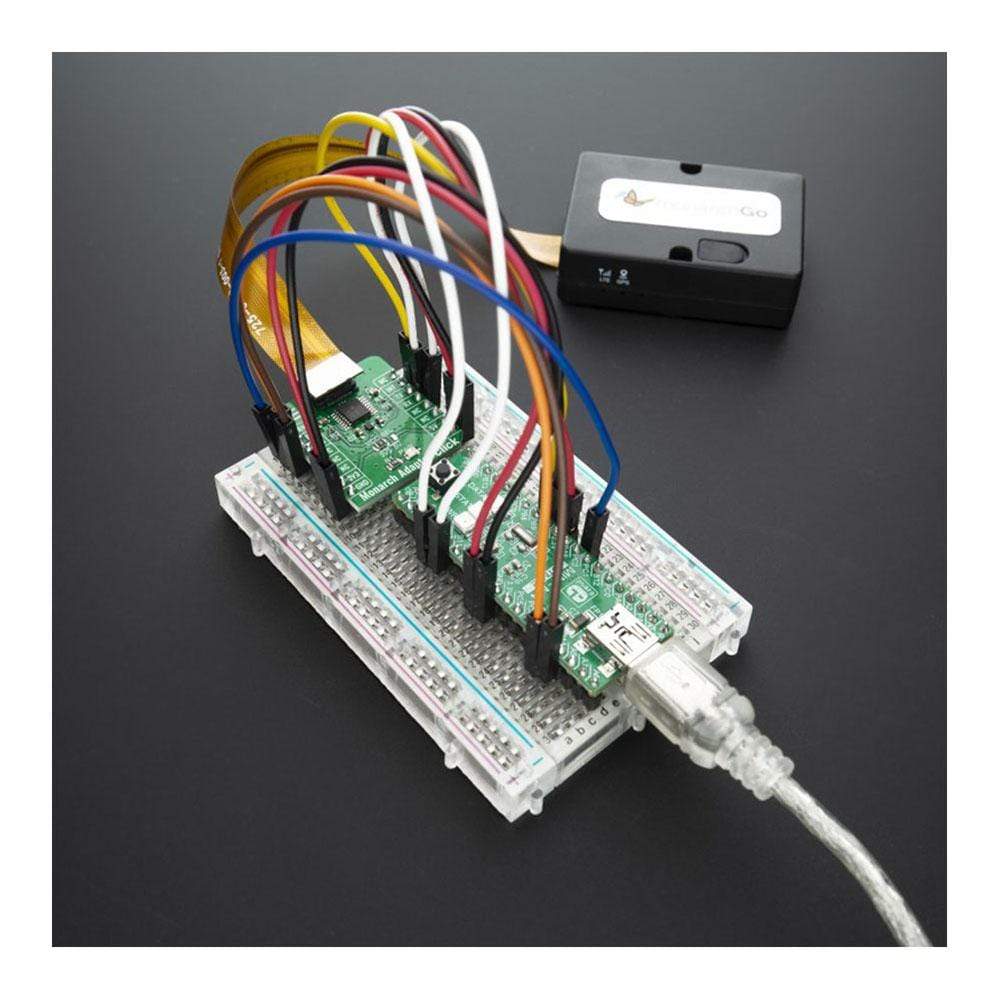
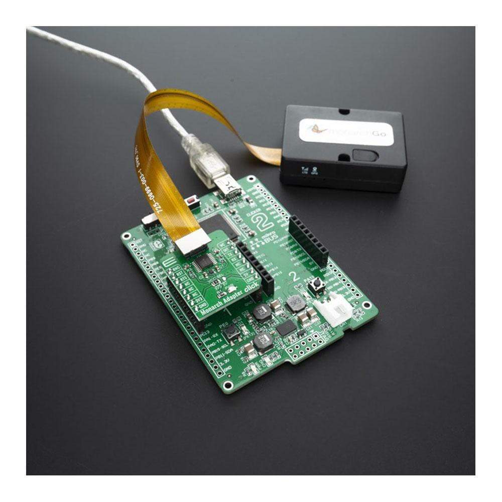
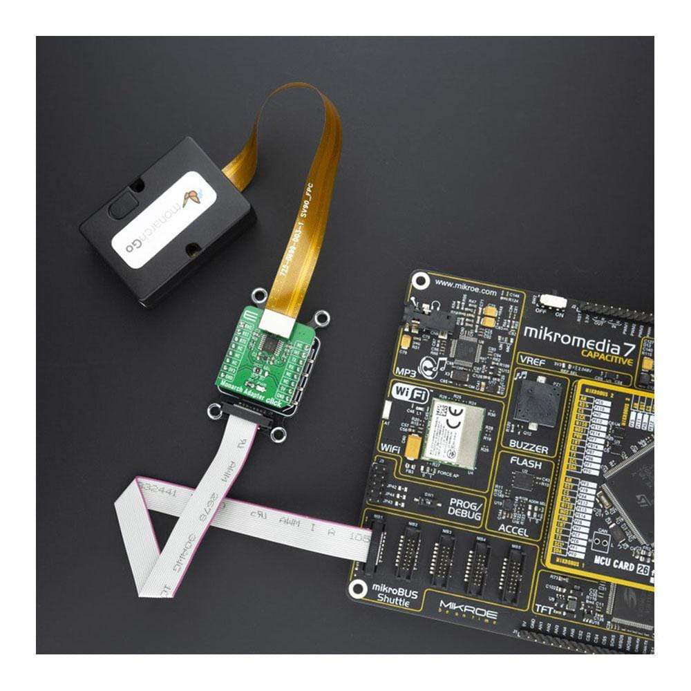
The Monarch Adapter Click Board™ is used to connect compatible Monarch Go LTE-M modems from Sequans to your development board or prototype device. This Click adapter provides a connection to the cloud server with AT commands. The Monarch Go LTE-M modem component with embedded antenna is perfectly suited for a broad range of IoT applications, including telemetry, vending machines, agriculture sensor applications, asset and transportation trackers, hardware tools, and home security monitoring applications.
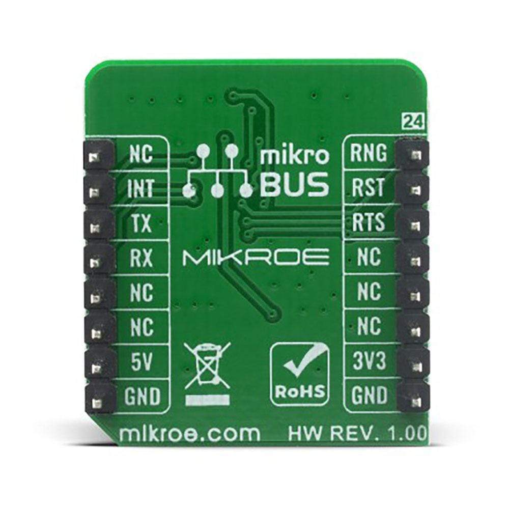
The Monarch Adapter Click Board™ is supported by a mikroSDK compliant library, which includes functions that simplify software development. This Click Board™ comes as a fully tested product, ready to be used on a system equipped with the mikroBUS™ socket.
Downloads
Das Monarch Adapter Click Board™ dient zum Verbinden kompatibler Monarch Go LTE-M-Modems von Sequans mit Ihrem Entwicklungsboard oder Prototypgerät. Dieser Click-Adapter ermöglicht eine Verbindung zum Cloud-Server mit AT-Befehlen. Die Monarch Go LTE-M-Modemkomponente mit integrierter Antenne eignet sich perfekt für eine breite Palette von IoT-Anwendungen, darunter Telemetrie, Verkaufsautomaten, landwirtschaftliche Sensoranwendungen, Anlagen- und Transport-Tracker, Hardware-Tools und Anwendungen zur Überwachung der Sicherheit zu Hause.
Das Monarch Adapter Click Board™ wird von einer mikroSDK-kompatiblen Bibliothek unterstützt, die Funktionen enthält, die die Softwareentwicklung vereinfachen. Dieses Click Board™ wird als vollständig getestetes Produkt geliefert und ist bereit für den Einsatz auf einem System, das mit der mikroBUS™ -Buchse ausgestattet ist.
| General Information | |
|---|---|
Part Number (SKU) |
MIKROE-4057
|
Manufacturer |
|
| Physical and Mechanical | |
Weight |
0.02 kg
|
| Other | |
EAN |
8606018717149
|
Frequently Asked Questions
Have a Question?
Be the first to ask a question about this.