


Mikroelektronika d.o.o.
Indexzähler Click Board
Indexzähler Click Board
SKU: MIKROE-4005
Verfügbarkeit für Abholungen konnte nicht geladen werden
Overview
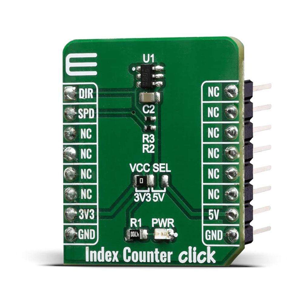
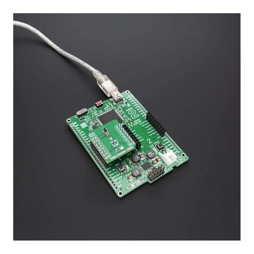
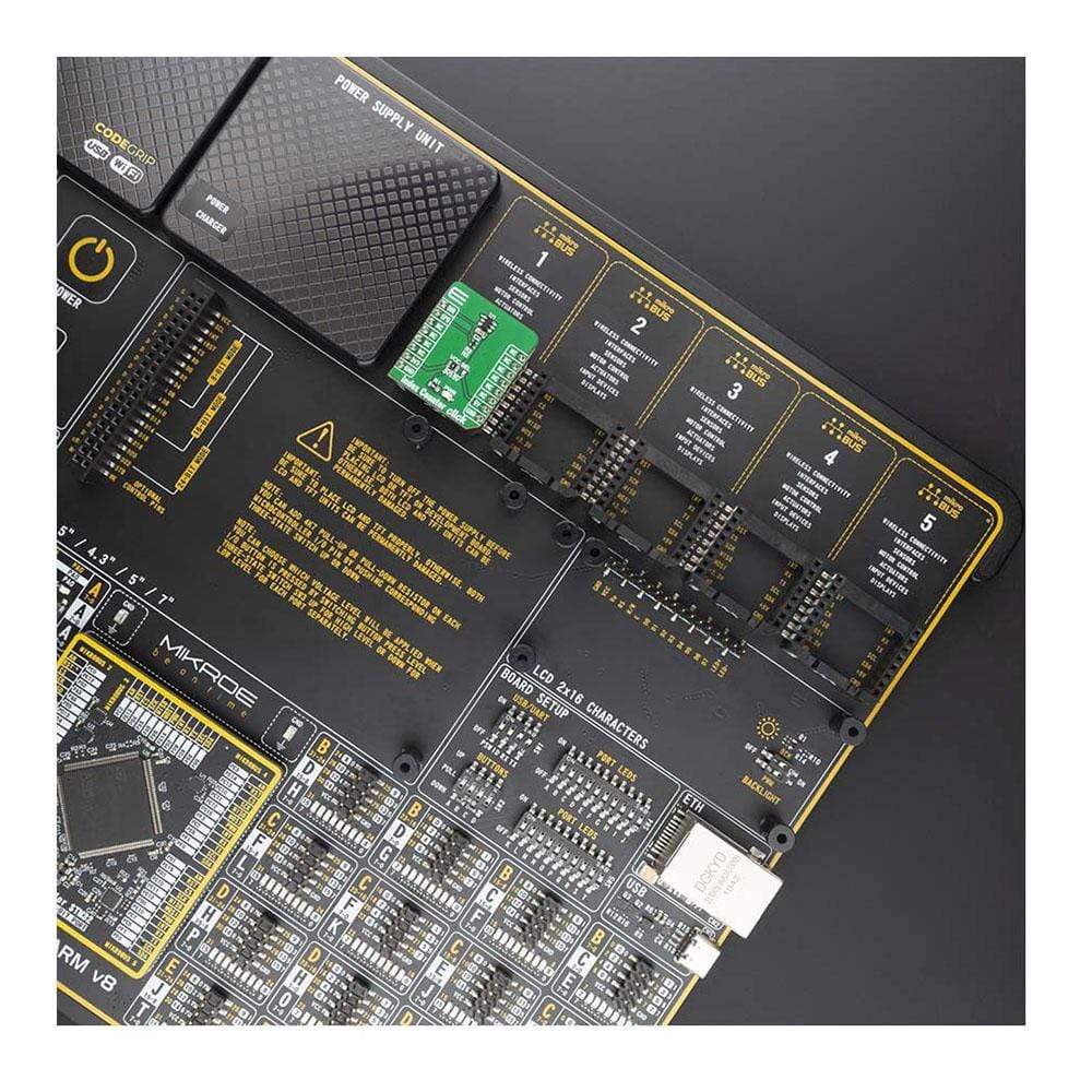
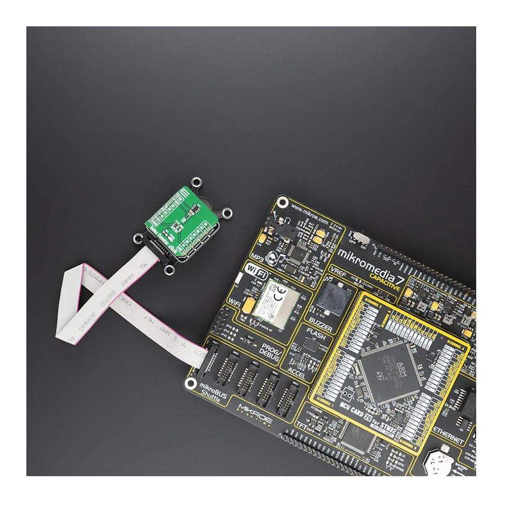
The Index Counter Click Board™ is a simple prototyping high precision Hall-Effect switch solution with direction detection. This board is hosting TLE4966K an integrated circuit dual Hall-effect sensor from Infineon. The sensor is designed specifically for highly accurate applications which use a rotating pole wheel since offers high sensitivity and high stability of the magnetic switching points. Since this sensor is based on two hall probes that provide information about the direction and speed of the moving wheel, this makes this product an excellent choice for applications such as index counting, rotational speed and direction applications, motor-driven position systems.
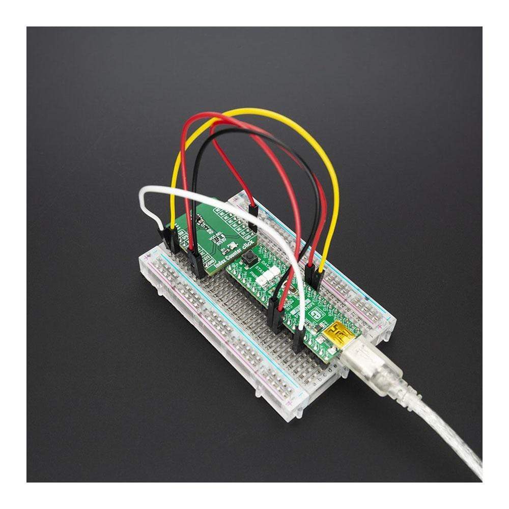
The Index Counter Click Board™ is supported by a mikroSDK compliant library, which includes functions that simplify software development. This Click Board™ comes as a fully tested product, ready to be used on a system equipped with the mikroBUS™ socket.
Downloads
Das Index Counter Click Board™ ist eine einfache, hochpräzise Hall-Effekt-Schalterlösung mit Richtungserkennung zum Prototyping. Diese Platine enthält TLE4966K, einen integrierten Dual-Hall-Effekt-Sensor von Infineon. Der Sensor wurde speziell für hochpräzise Anwendungen mit rotierendem Polrad entwickelt, da er eine hohe Empfindlichkeit und Stabilität der magnetischen Schaltpunkte bietet. Da dieser Sensor auf zwei Hall-Sonden basiert, die Informationen über die Richtung und Geschwindigkeit des sich bewegenden Rads liefern, ist dieses Produkt eine ausgezeichnete Wahl für Anwendungen wie Indexzählung, Rotationsgeschwindigkeits- und Richtungsanwendungen sowie motorgetriebene Positionssysteme.
Der Index Counter Click Board™ wird von einer mikroSDK-kompatiblen Bibliothek unterstützt, die Funktionen enthält, die die Softwareentwicklung vereinfachen. Dieses Click Board™ wird als vollständig getestetes Produkt geliefert und ist bereit für den Einsatz auf einem System, das mit der mikroBUS™-Buchse ausgestattet ist.
| General Information | |
|---|---|
Part Number (SKU) |
MIKROE-4005
|
Manufacturer |
|
| Physical and Mechanical | |
Weight |
0.016 kg
|
| Other | |
EAN |
8606018718320
|
Frequently Asked Questions
Have a Question?
Be the first to ask a question about this.