


Mikroelektronika d.o.o.
6DOF IMU 10 Click-Platine
6DOF IMU 10 Click-Platine
SKU: MIKROE-3934
Verfügbarkeit für Abholungen konnte nicht geladen werden


Overview
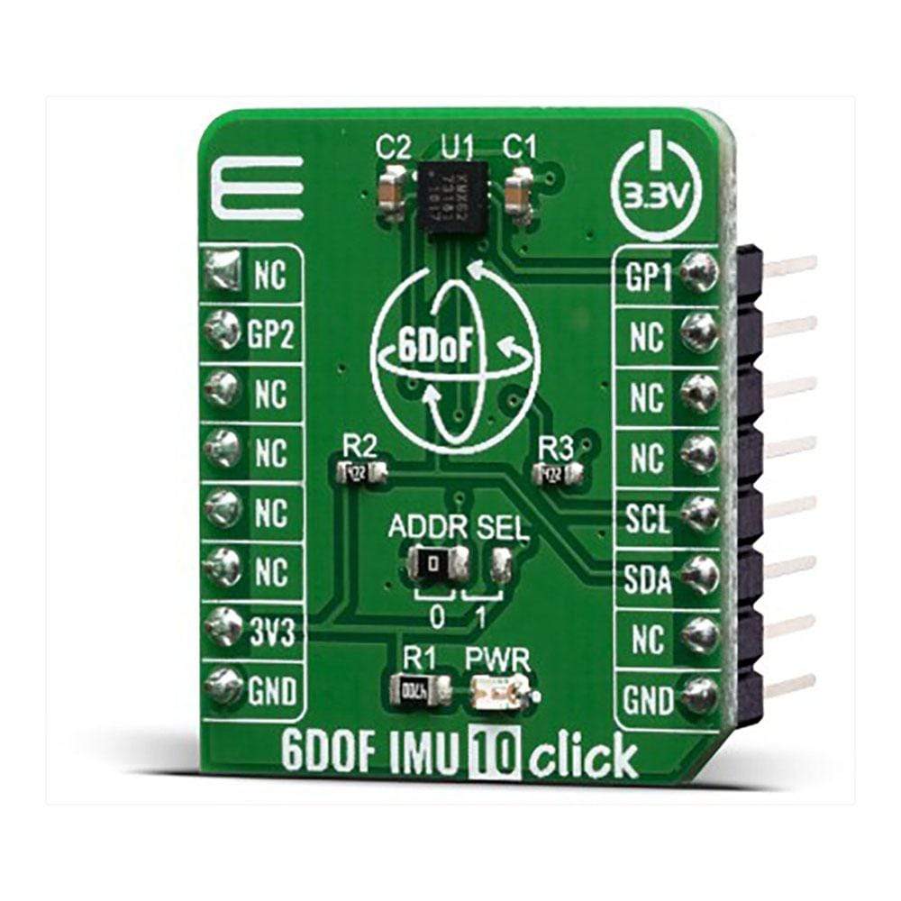
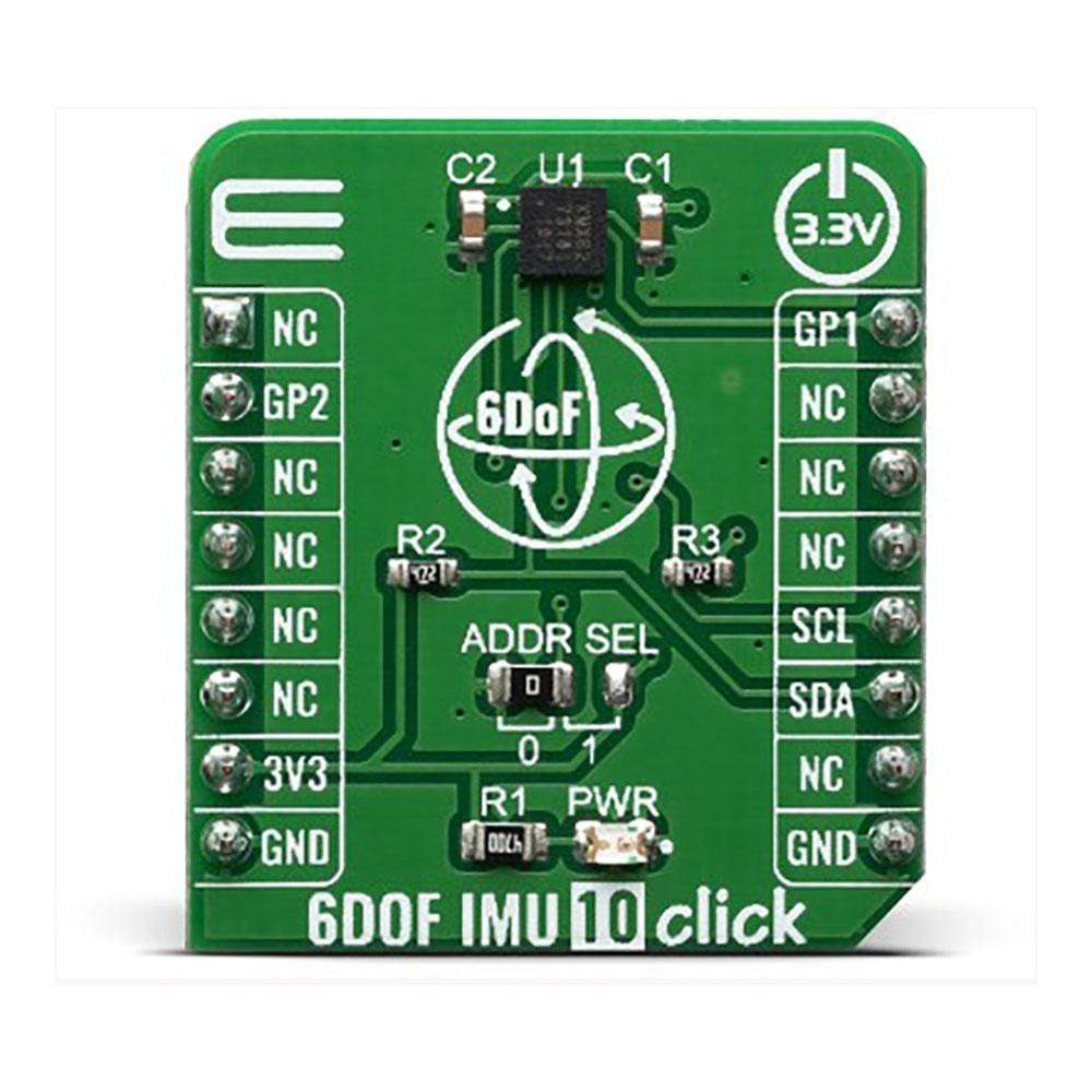
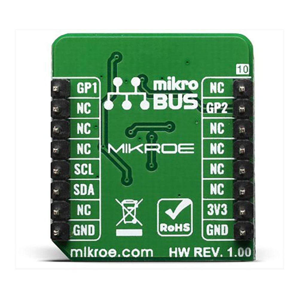
The 6DOF IMU 10 Click Board™ is a 6 Degrees-of-Freedom inertial sensor module, that features a KMX62 sensor which consists of a tri-axial magnetometer (range ±2g / ±4g / ±8g / ±16g) plus a triaxial accelerometer (±1200µT). The accelerometer and magnetometer data can be accumulated in an internal 384-byte FIFO buffer and transmitted to the Application Processor. This Click Board™ can be used for applications that require movement and orientation features, navigation, such as screen orientation, machine/vibration analysis, game playing.
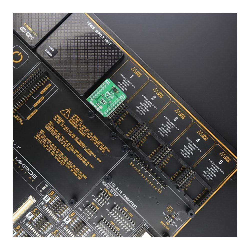
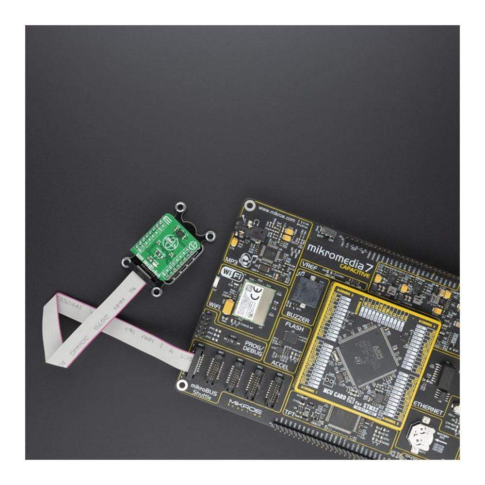
The 6DOF IMU 10 Click is supported by a mikroSDK compliant library, which includes functions that simplify software development. This Click Board™ comes as a fully tested product, ready to be used on a system equipped with the mikroBUS™ socket.
Downloads
Das 6DOF IMU 10 Click Board™ ist ein Trägheitssensormodul mit 6 Freiheitsgraden, das über einen KMX62-Sensor verfügt, der aus einem dreiachsigen Magnetometer (Bereich ±2 g / ±4 g / ±8 g / ±16 g) und einem dreiachsigen Beschleunigungsmesser (±1200 µT) besteht. Die Daten des Beschleunigungsmessers und des Magnetometers können in einem internen 384-Byte-FIFO-Puffer gesammelt und an den Anwendungsprozessor übertragen werden. Dieses Click Board™ kann für Anwendungen verwendet werden, die Bewegungs- und Orientierungsfunktionen, Navigation, wie z. B. Bildschirmorientierung, Maschinen-/Vibrationsanalyse und Spiele erfordern.
Das 6DOF IMU 10 Click wird von einer mikroSDK-kompatiblen Bibliothek unterstützt, die Funktionen enthält, die die Softwareentwicklung vereinfachen. Dieses Click Board™ wird als vollständig getestetes Produkt geliefert und ist bereit für den Einsatz auf einem System, das mit der mikroBUS™-Buchse ausgestattet ist.
| General Information | |
|---|---|
Part Number (SKU) |
MIKROE-3934
|
Manufacturer |
|
| Physical and Mechanical | |
Weight |
0.017 kg
|
| Other | |
EAN |
8606018718924
|
Frequently Asked Questions
Have a Question?
Be the first to ask a question about this.