


Mikroelektronika d.o.o.
H-Bridge 4 Click-Platine
H-Bridge 4 Click-Platine
SKU: MIKROE-3787
Verfügbarkeit für Abholungen konnte nicht geladen werden


Overview
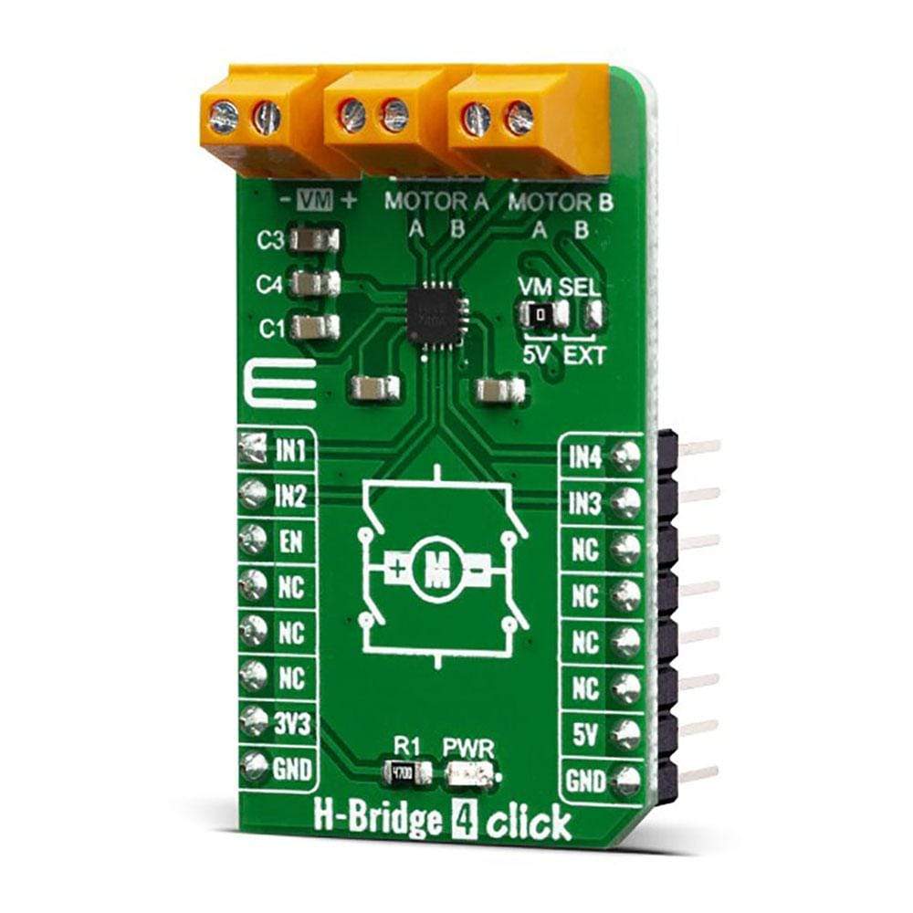
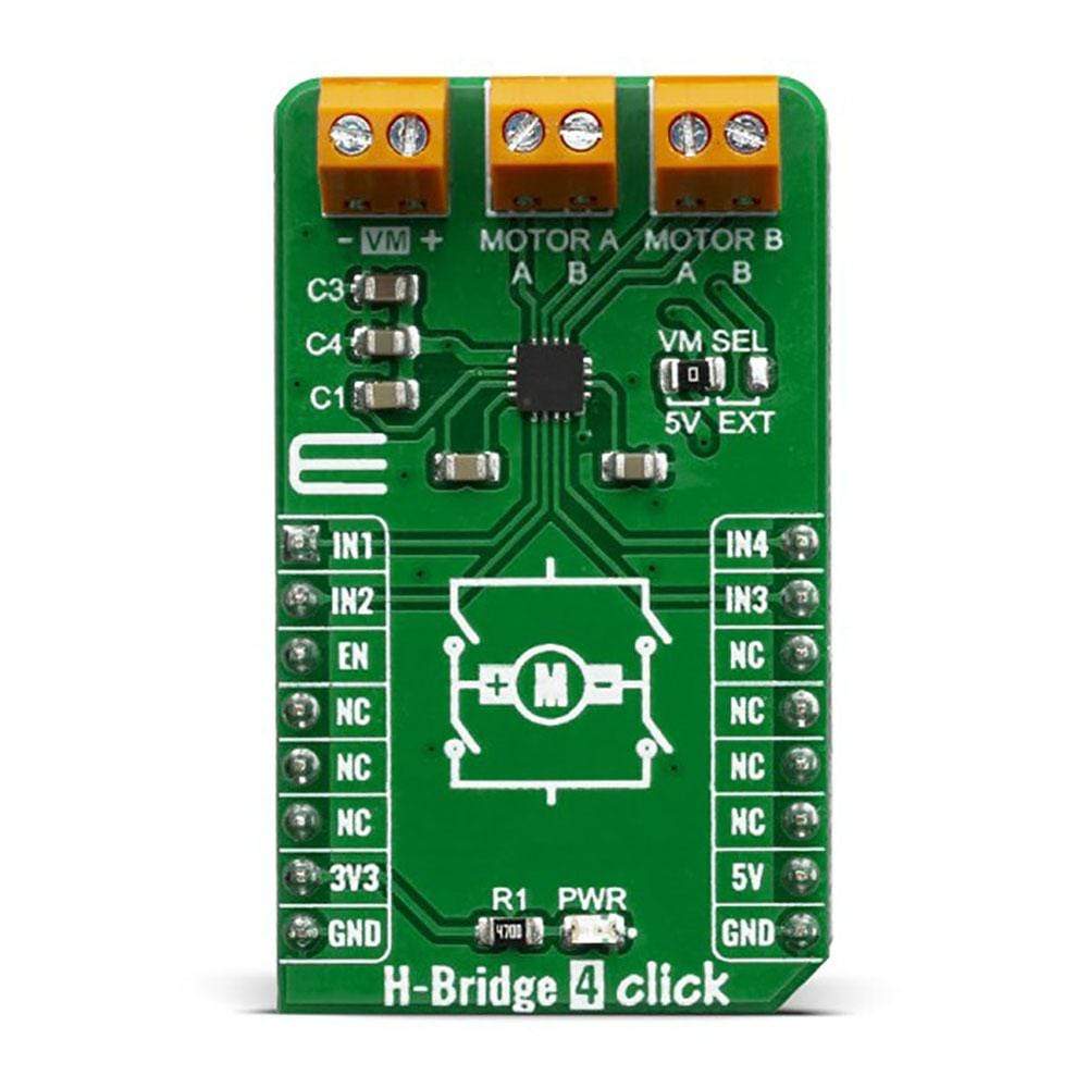
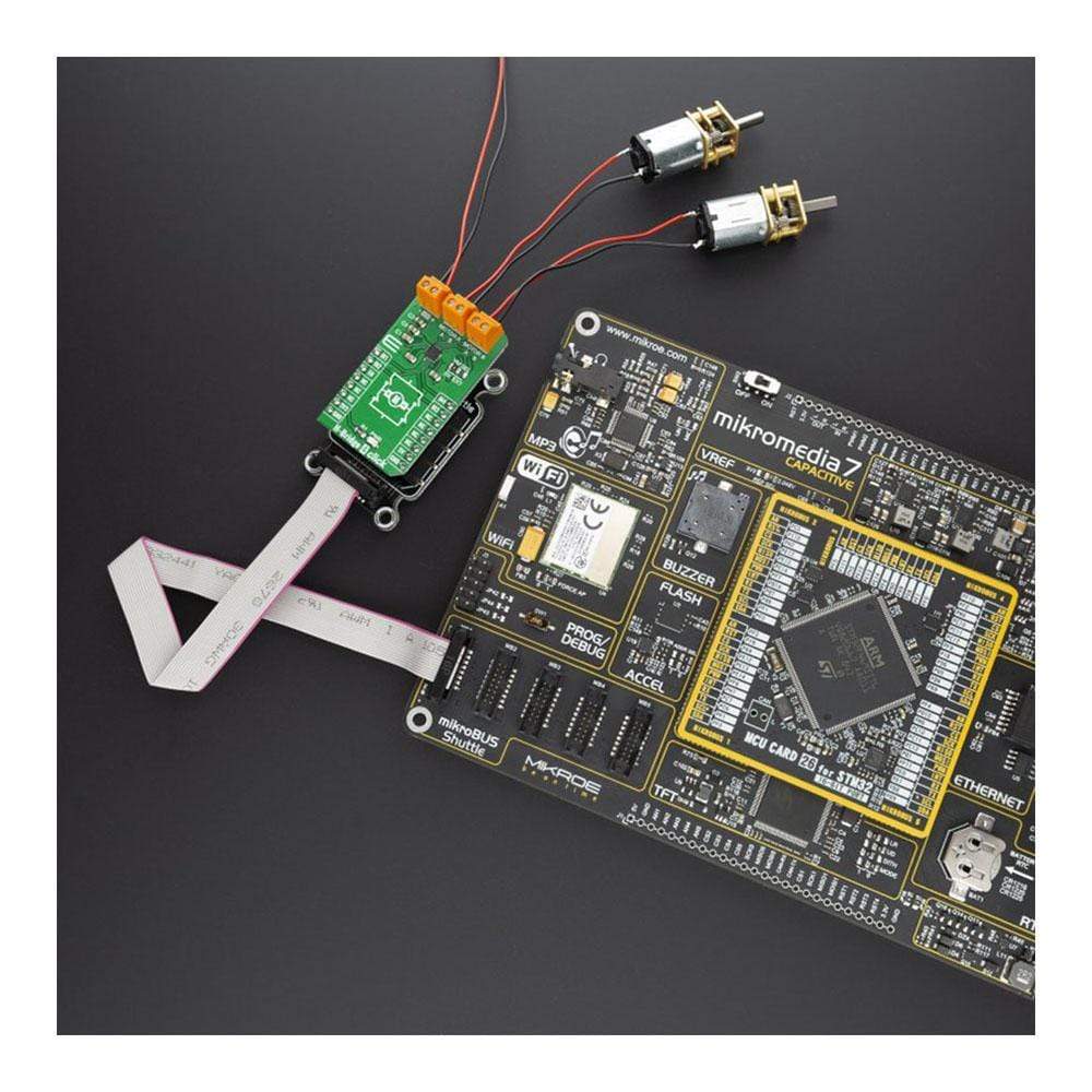
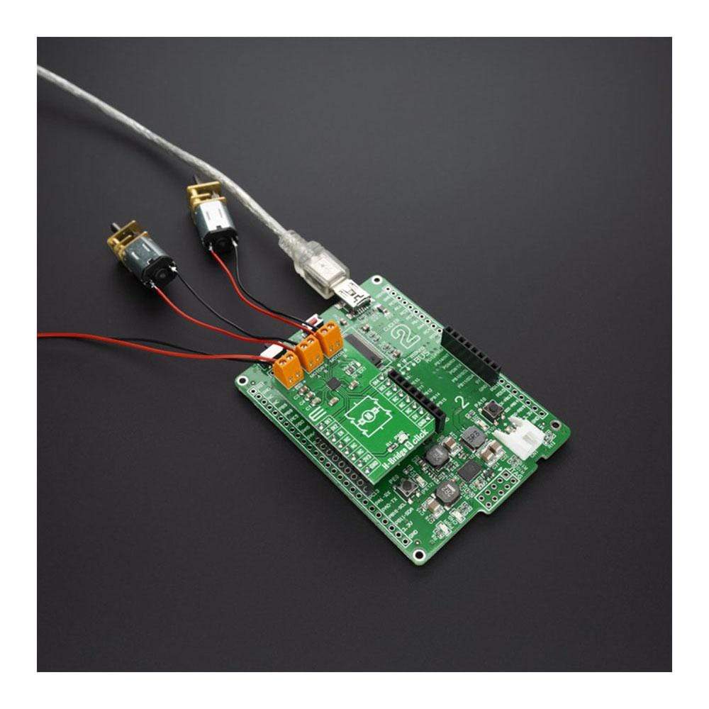
The H-Bridge 4 Click Board™ contains the AP1010AEN, which is a two-channel H-Bridge motor driver compatible with a motor operating voltage up to 18V and can drive two DC motors or one stepper motor. The protection circuit has an under-voltage lockout circuit, thermal shutdown circuit, and over-current protection circuit, and the over-current protection circuit can be disabled with the DIS OCP terminal.
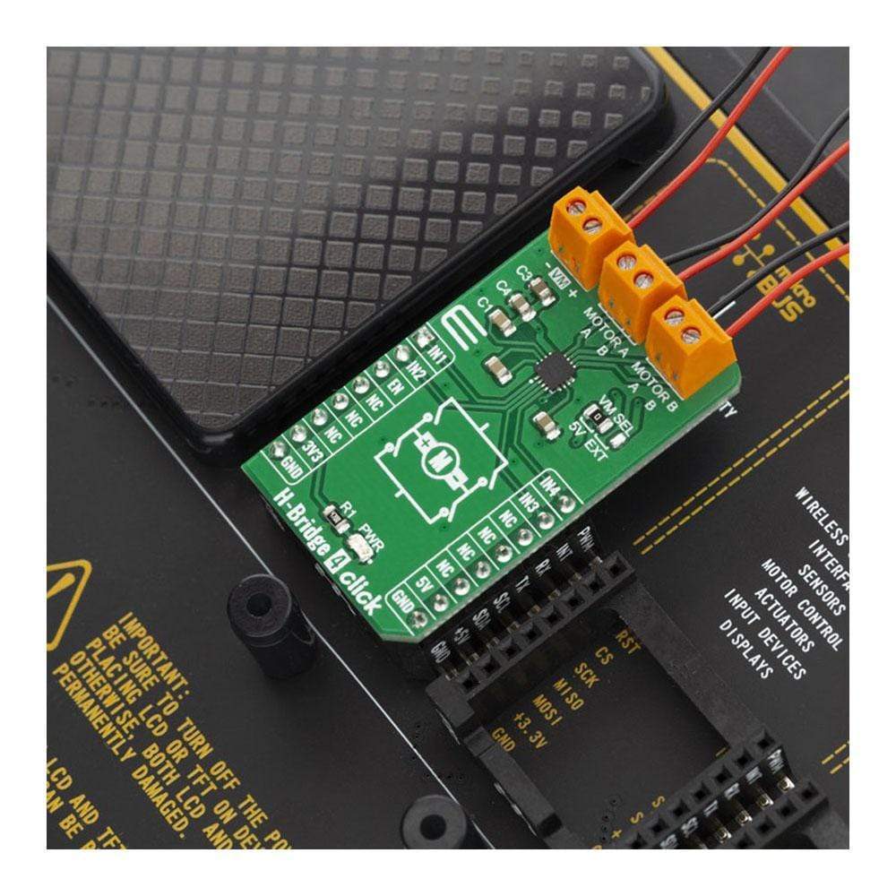
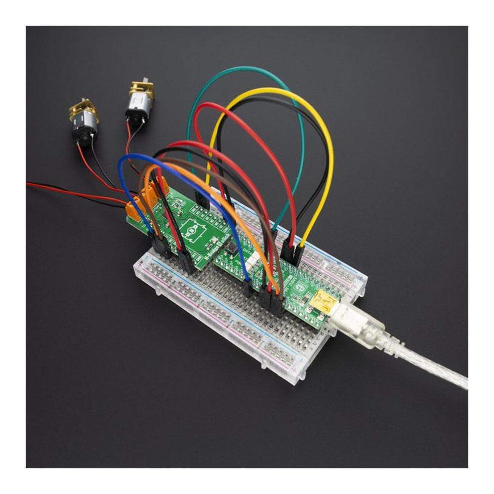
The H-Bridge 4 Click Board™ supports multiple connection options and can be used in different application setups which might include DC or Stepper motors.
Downloads
Das H-Bridge 4 Click Board™ enthält den AP1010AEN, einen zweikanaligen H-Brücken-Motortreiber, der mit einer Motorbetriebsspannung von bis zu 18 V kompatibel ist und zwei Gleichstrommotoren oder einen Schrittmotor antreiben kann. Die Schutzschaltung verfügt über eine Unterspannungs-Sperrschaltung, eine thermische Abschaltschaltung und eine Überstromschutzschaltung. Die Überstromschutzschaltung kann mit dem DIS OCP-Anschluss deaktiviert werden.
Das H-Bridge 4 Click Board™ unterstützt mehrere Verbindungsoptionen und kann in verschiedenen Anwendungskonfigurationen verwendet werden, die Gleichstrom- oder Schrittmotoren umfassen können.
| General Information | |
|---|---|
Part Number (SKU) |
MIKROE-3787
|
Manufacturer |
|
| Physical and Mechanical | |
Weight |
0.019 kg
|
| Other | |
EAN |
8606018719891
|
Frequently Asked Questions
Have a Question?
Be the first to ask a question about this.