Ladegerät 12 Click-Platine
Overview
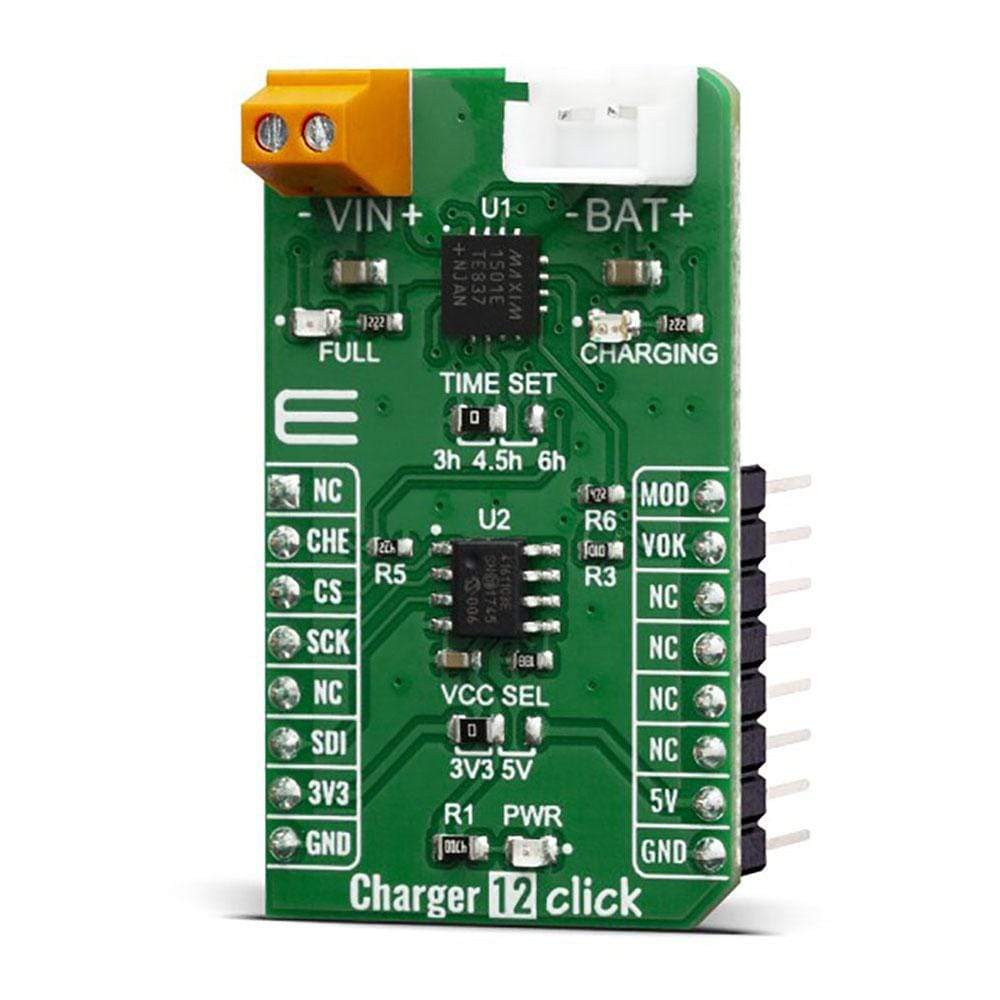
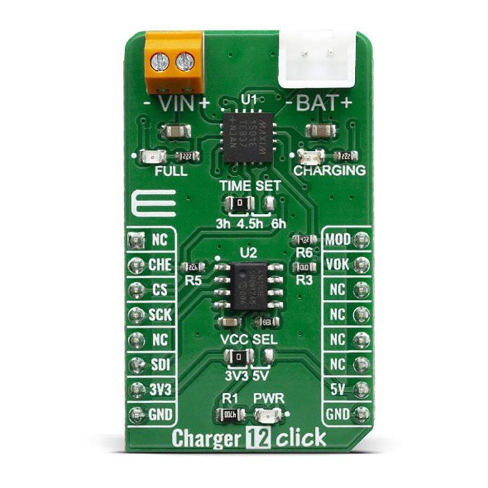
Das Charger 12 Click Board™ ist ein Ladegerät für eine einzelne Lithium-Ionen-Zelle (Li+) oder drei NiMH/NiCd-Zellen. Dieses Click Board™ kann für kostengünstige Li-Ion-Akkuladegeräte oder Elektrowerkzeuge, Spielzeuge, Backup-Energiespeicherlösungen usw. verwendet werden. Das Charger 12 Click Board™ basiert auf dem MAX1501-Controller, der über einige zusätzliche Funktionen verfügt, die ein Laden ohne allzu großen Aufwand ermöglichen.
Das Charger 12 Click Board™ verfügt über eine Ladestromregelung, die die SPI-Schnittstelle über MCP4161 IC nutzt, ein digitales 8-Bit-Potentiometer. Auf der Platine befinden sich eine Power-LED und zwei zusätzliche LEDs, die für Ladeanzeigen verwendet werden können.
As a Lithium Ion batteries require a very accurate current and voltage for charging, the Charger 12 Click Board™ can be a perfect solution for such a task. Charger 12 Click Board™ is equipped with a highly integrated Li-Ion battery charger, supporting intelligent, constant-current, constant voltage (CCCV), temperature-regulated battery charger charges a single lithium-ion (Li+) cell or three-cell NiMH/NiCd batteries. This Click Board™ has a charging current control IC over SPI interface which ensures perfect and efficient charging. The Charger 12 Click Board™ can be used as a part of the power supply and distribution system in many applications: different kinds of handheld appliances, portable media players, portable audio players, and other general-purpose battery-operated electronic devices.
How Does The Charger 12 Click Board™ Work?
The Charger 12 Click Board™ is based on the MAX1501 - highly Integrated, linear battery charger with thermal regulation for portable applications, from Maxim Integrated. MAX1501 is an efficient Lithium ion battery charger, thanks to Microprocessor-Controlled specific charge algorithms for Li-Ion batteries to achieve optimal capacity and safety in shortest charging time possible. Along with its small physical size, the low number of external components makes this IC ideally suitable for various applications. The 4.2V factory preset reference voltage simplifies design. The fast charge constant current is set by a digital potentiometer. On the Charger 12 Click Board™ it is MCP4161 – an 8-bit digital potentiometer from Microchip, with external 1.5KΩ resistor in series. Thanks to proprietary programmable die temperature regulation, MAX1501 can limit the charge current based on the temperature during high-power or high ambient conditions. This thermal regulation optimizes the charge cycle time while maintaining device reliability.
The MAX1501 IC is designed with reliability in mind: the IC prevents draining the battery below the critical level, protects it from overheating (if thermistor is used), offers prequel charging (for deeply depleted batteries), features an over-voltage protection, charging status monitoring and so on.
The Charger 12 Click Board™ itself is equipped with a set of indicators used to monitor both charging process and power distribution.
- CHARGE LED indicates the charge-in-progress status.
- FAULT LED indicates an error during charging process.
The digital potentiometer on the Charger 12 Click Board™ is MCP4161 which offers a wide range of product offerings using a SPI interface. WiperLock technology allows application-specific calibration settings to be secured in EEPROM. This digital pot is tied with charger IC over its wiper (P0W) pin. By assigning values on MCP4161 from 0 to 10 kilo ohms battery charging can be controlled. As there is a 1.5K resistor in series it can never be 0 ohms on MAX1501 chargers PROG pin. However, maximum resistance cannot exceed 11.5 kiloohms. Fast charging can be regulated with 10K on PROG pin to get 130 mA. To get 1000 mA digital potentiometer needs to go down to 0 ohm, along with external resistor, which makes 1,5 K. Communication with digital potentiometer on the Charger 12 Click Board™ and that way controlling the charger is done through SPI interface.
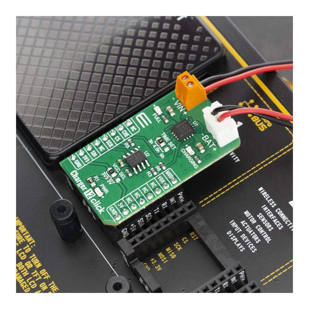
On the left side of the Charger 12 Click Board™ is an input screw terminal with corresponding markings, where the recommended external voltage of 6V can be applied. The left screw terminal is reserved for a Lithium Iron Phosphate battery with GND and VBAT+ markings. When connected to power source, the green PWR LED will indicate it. Red LED1 and green LED2 can be used for visual charge monitoring. As those two LEDs are multipurpose, they can be used for various things.
The voltage range which can be used to power up the BATT-MON Click Board™, allows for it to work with both 3.3V and 5V capable MCUs. It can be selected by soldering a small SMD jumper, labelled as VCC SEL to the correct position.
SPECIFICATIONS
Type | Battery charger |
Applications | The Charger 12 Click Board™ is a perfect choice for development lithium-ion (Li+) cell or three-cell NiMH/NiCd battery charging applications. |
On-board modules | MAX1501, highly Integrated, linear battery charger with thermal regulation for portable applications, from Maxim Integrated. |
Key Features | Intelligent, constant-current, constant voltage (CCCV), temperature-regulated battery charger |
Interface | GPIO,SPI |
Compatibility | mikroBUS |
Click Board™ size | M (42.9 x 25.4 mm) |
Input Voltage | 3.3V or 5V |
PINOUT DIAGRAM
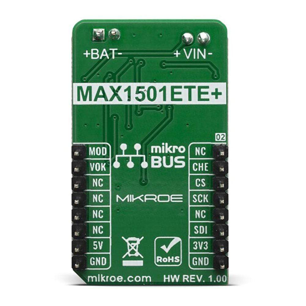
This table shows how the pinout on the Charger 12 Click Board™ corresponds to the pinout of the mikroBUS socket (the latter shown in the two middle columns).
Notes | Pin | Pin | Notes | ||||
---|---|---|---|---|---|---|---|
NC | 1 | AN | PWM | 16 | MOD | Mode Select Input | |
Charging Enable | CHE | 2 | RST | INT | 15 | VOK | Input Voltage Range |
Chip Enable | SDN | 3 | CS | RX | 14 | NC | |
Serial Clock | SCK | 4 | SCK | TX | 13 | NC | |
NC | 5 | MISO | SCL | 12 | NC | ||
Serial Data In | SDI | 6 | MOSI | SDA | 11 | NC | |
Power Supply | 3.3V | 7 | 3.3V | 5V | 10 | 5V | Power Supply |
Ground | GND | 8 | GND | GND | 9 | GND | Ground |
Software Support
We provide a library for the Charger 12 Click Board™ on our LibStock page, as well as a demo application (example), developed using MikroElektronika compilers. The demo can run on all the main MikroElektronika development boards.
Library Description
Library contains functions for getting and setting GPIO pin states Library contains function for mode selection Library contains function for SPI transfer operation Library contains function for SPI get register operation Library contains functions for incrementing and decrementing wiper position
Key Functions
uint8_t charger12_mode_select( uint8_t mode_select )
- selects device operation mode by setting RST(CHGEN) and PWM(MODE) pinsvoid charger12_spi_increment_wiper( void )
- increments wiper position by sending 8bit increment wiper commandvoid charger12_spi_decrement_wiper( void )
- decrements wiper position by sending 8bit decrement wiper command
Example Description
The application is composed of three sections :
- System Initialization - Initializes GPIO pins, SPI and LOG modules
- Application Initialization - Initializes the SPI driver
- Application Task - Executes additional functions based on user input
void applicationTask( ) { uart_ready = UART_Data_Ready( ); if (uart_ready == 1) { uart_char = UART_Read( ); switch (uart_char) { case '+' : { charger12_case_Plus( ); break; } case '-' : { charger12_case_Minus( ); break; } case '1' : { charger12_case_One( ); break; } case '2' : { charger12_case_Two( ); break; } case '3' : { charger12_case_Three( ); break; } case '4' : { charger12_case_Four( ); break; } default : { mikroBUS_logWrite( "> Invalid command", _LOG_LINE ); break; } } } }
Additional Functions :
- charger12_case_Plus() - Increments Wiper position
- charger12_case_Minus() - Decrements Wiper position
- charger12_case_One() - Selects 1st mode of operation
- charger12_case_Two() - Selects 2nd mode of operation
- charger12_case_Three() - Selects 3rd mode of operation
- charger12_case_Four() - Selects 4th mode of operation
The full application code, and ready to use projects can be found on our LibStock page.
Other mikroE Libraries used in the example:
- SPI
- UART
- Conversions
Additional Notes and Information
Depending on the development board you are using, you may need a USB UART Click Board™, USB UART 2 Click Board™ or RS232 Click Board™ to connect to your PC, for development systems with no UART to USB interface available on the board. The terminal available in all MikroElektronika compilers, or any other terminal application of your choice, can be used to read the message.
MikroSDK
The Charger 12 Click Board™ is supported with mikroSDK - MikroElektronika Software Development Kit. To ensure proper operation of mikroSDK compliant Click Board™ demo applications, mikroSDK should be downloaded from the LibStock and installed for the compiler you are using.
Frequently Asked Questions
Have a Question?
Be the first to ask a question about this.