


Mikroelektronika d.o.o.
Thermostat 3 Click-Platine
Thermostat 3 Click-Platine
SKU: MIKROE-3724
Verfügbarkeit für Abholungen konnte nicht geladen werden
Overview
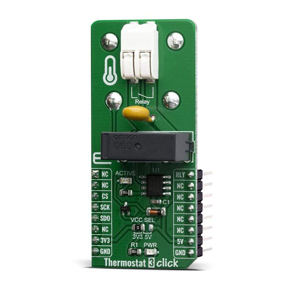
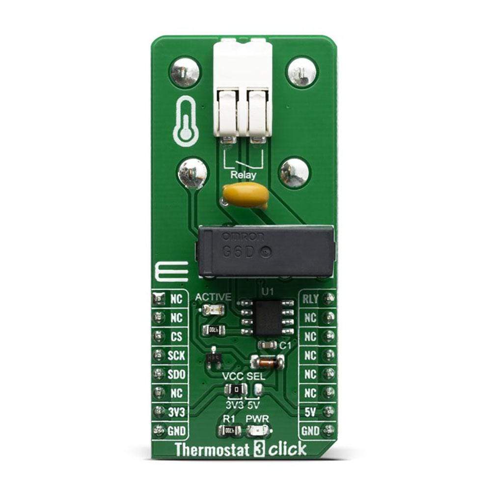
The Thermostat 3 Click Board™ is a general-purpose thermostat Click Board™ designed to be used with any temperature sensor based on the MAX31855 sensor design. The Click Board™ is equipped with a 2-pin female socket for thermocouple connection.
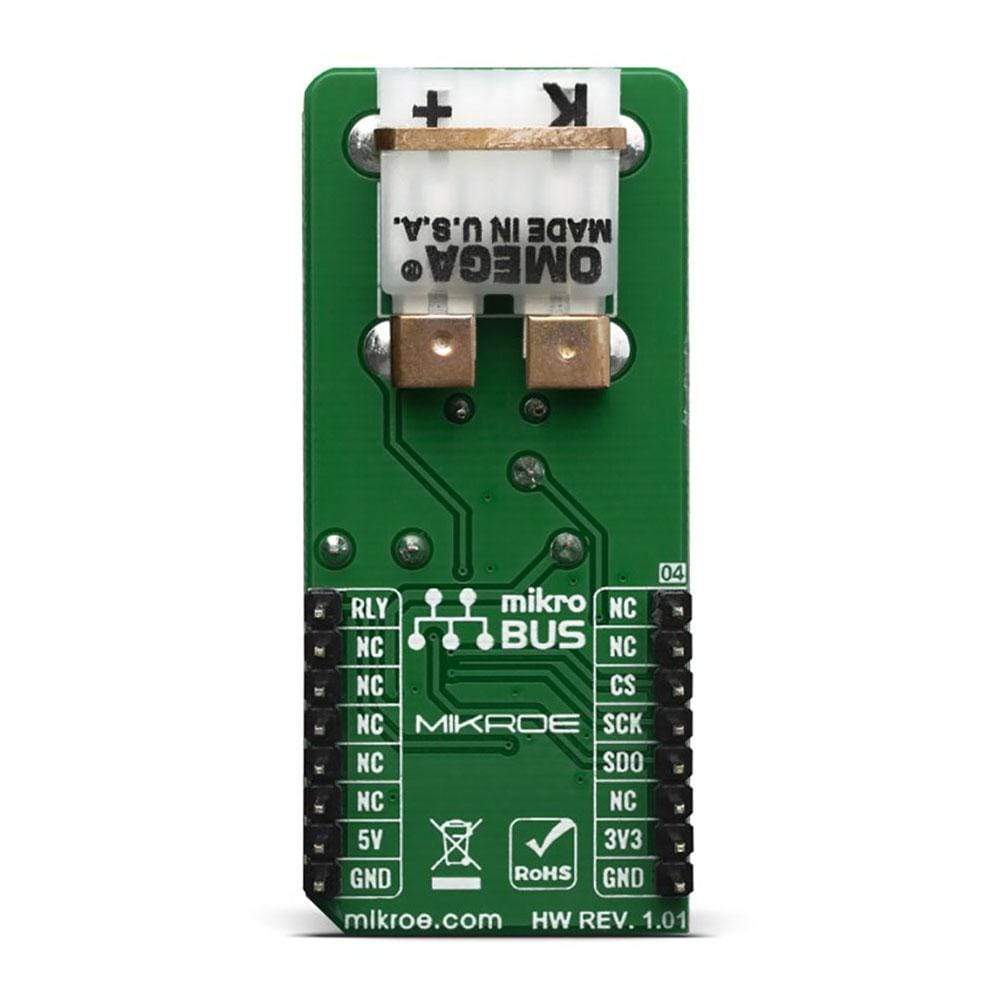
The K-type thermocouple can be connected directly into the socket, allowing the MAX31855 to take care of the signal-conditioning and output the absolute temperature value. The Click Board™ also contains a high-quality relay from Omron, that can be used to open or close an electric circuit. Despite its small size, it can be used with voltage up to 30VDC/220AC and current up to 5A.
Downloads
Das Thermostat 3 Click Board™ ist ein universelles Thermostat Click Board™, das für die Verwendung mit jedem Temperatursensor basierend auf dem MAX31855-Sensordesign entwickelt wurde. Das Click Board™ ist mit einer 2-poligen Buchse für den Thermoelementanschluss ausgestattet.
Das Thermoelement vom Typ K kann direkt an die Buchse angeschlossen werden, sodass der MAX31855 die Signalaufbereitung übernimmt und den absoluten Temperaturwert ausgibt. Das Click Board™ enthält außerdem ein hochwertiges Relais von Omron, mit dem ein Stromkreis geöffnet oder geschlossen werden kann. Trotz seiner geringen Größe kann es mit Spannungen bis zu 30 VDC/220 AC und Stromstärken bis zu 5 A verwendet werden.
| General Information | |
|---|---|
Part Number (SKU) |
MIKROE-3724
|
Manufacturer |
|
| Physical and Mechanical | |
Weight |
0.026 kg
|
| Other | |
EAN |
8606018716746
|
Frequently Asked Questions
Have a Question?
Be the first to ask a question about this.