


Mikroelektronika d.o.o.
STSPIN233 Click-Platine
STSPIN233 Click-Platine
SKU: MIKROE-3546
Verfügbarkeit für Abholungen konnte nicht geladen werden
Overview
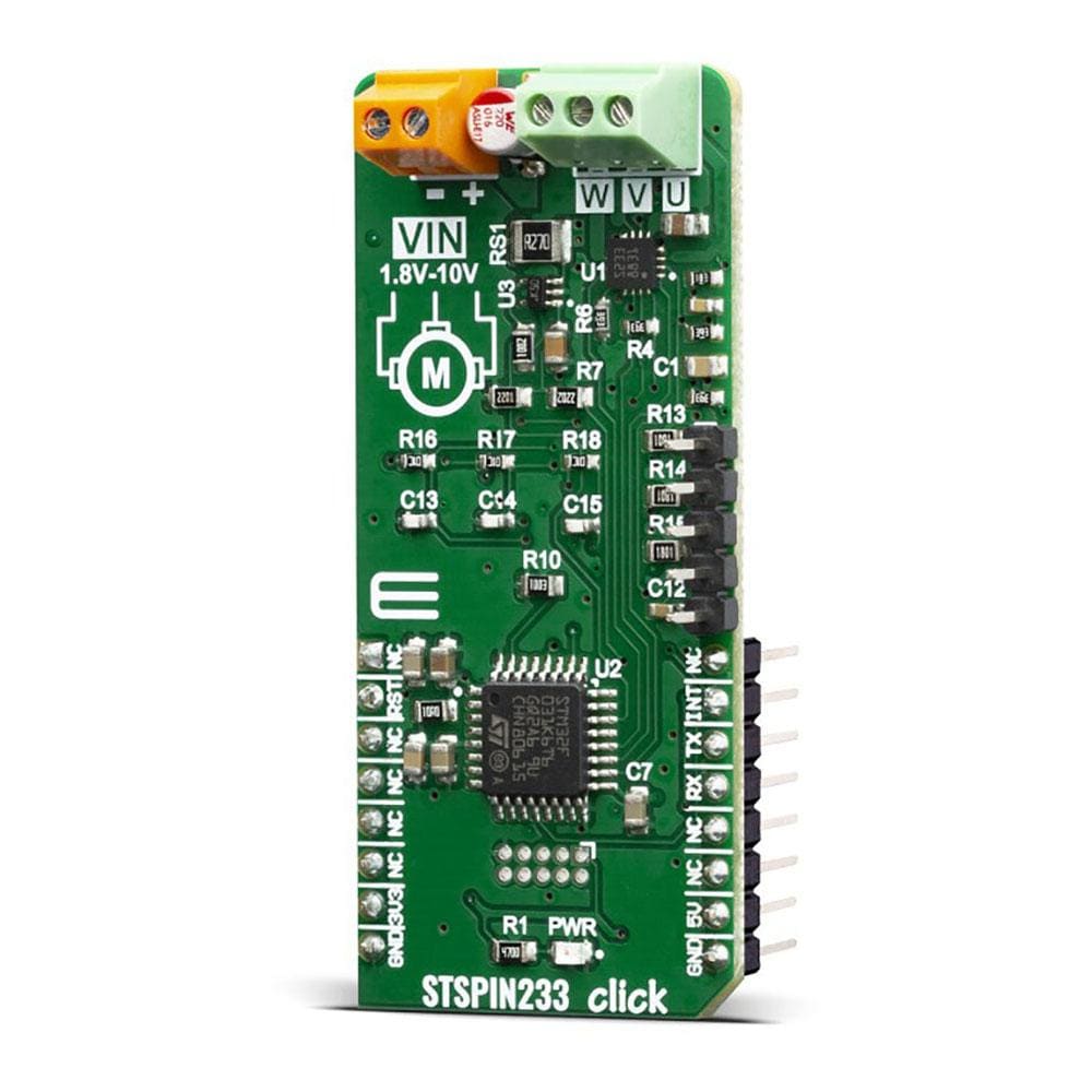
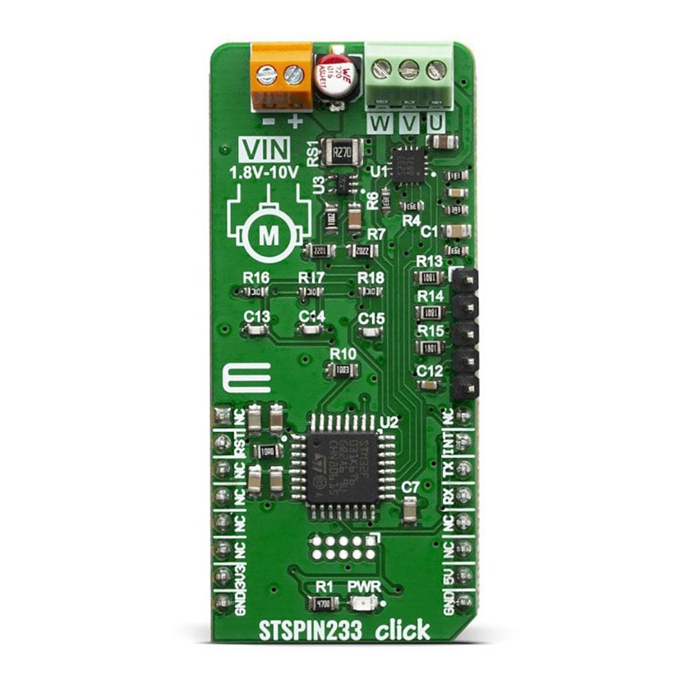
The STSPIN233 Click Board™ is a complete solution for a 3-phase integrated motor driver, based on the STSPIN233, Low voltage 3-phase integrated motor driver. It is optimized for battery-powered, low voltage motor driving applications, featuring the lowest standby current available on the market (max 80 nA).
The STSPIN233 is a high-efficiency motor driver, featuring low ON resistance MOSFETs as the output stage, and extremely low leakage current (max 1µA). Its output stage implements the PWM current control with fixed OFF time, along with a full set of protection features. The device can be used with the step motor voltage ranging from 1.8V to 10V, and current up to 1.3A per bridge.
Downloads
Der STSPIN233 Click Board™ ist eine Komplettlösung für einen integrierten 3-Phasen-Motortreiber, basierend auf dem STSPIN233, einem integrierten 3-Phasen-Niederspannungs-Motortreiber. Es ist für batteriebetriebene Niederspannungs-Motorantriebsanwendungen optimiert und verfügt über den niedrigsten Standby-Strom auf dem Markt (max. 80 nA).
Der STSPIN233 ist ein hocheffizienter Motortreiber mit MOSFETs mit niedrigem Einschaltwiderstand als Ausgangsstufe und extrem niedrigem Leckstrom (max. 1 µA). Seine Ausgangsstufe implementiert die PWM-Stromsteuerung mit fester Ausschaltzeit sowie einen vollständigen Satz von Schutzfunktionen. Das Gerät kann mit einer Schrittmotorspannung von 1,8 V bis 10 V und einem Strom von bis zu 1,3 A pro Brücke verwendet werden.
| General Information | |
|---|---|
Part Number (SKU) |
MIKROE-3546
|
Manufacturer |
|
| Physical and Mechanical | |
Weight |
0.018 kg
|
| Other | |
EAN |
8606018715725
|
Frequently Asked Questions
Have a Question?
Be the first to ask a question about this.