


Mikroelektronika d.o.o.
MIC 2 Click-Platine
MIC 2 Click-Platine
SKU: MIKROE-3445
Verfügbarkeit für Abholungen konnte nicht geladen werden


Overview
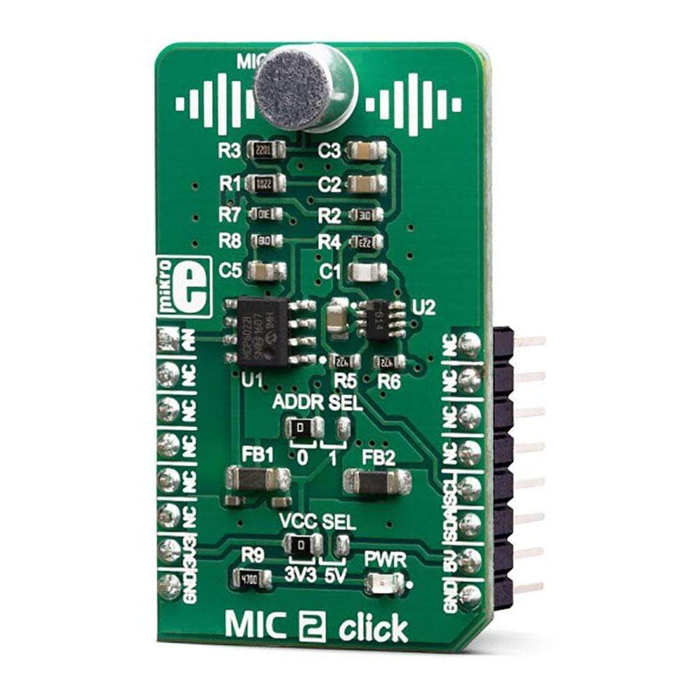
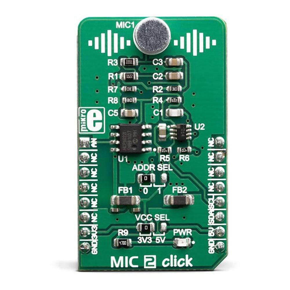
The MIC 2 Click Board™ is equipped with a small electret microphone, accompanied by a suitable preamplifier circuit. The small electret microphone is not capable of providing sufficient line-level output; therefore, the pre-amp has to be used. The pre-amp circuit consists of a dual op-amp and a digitally controlled potentiometer IC. Thanks to the AD5171, it is possible to control the feedback loop gain of the MCP6022 op-amp over the I2C interface, in 64 discrete steps. The AD5171 digital potentiometer IC can lock-out its wiper by means of OTP fuse bit: once locked, it will permanently retain the programmed value.
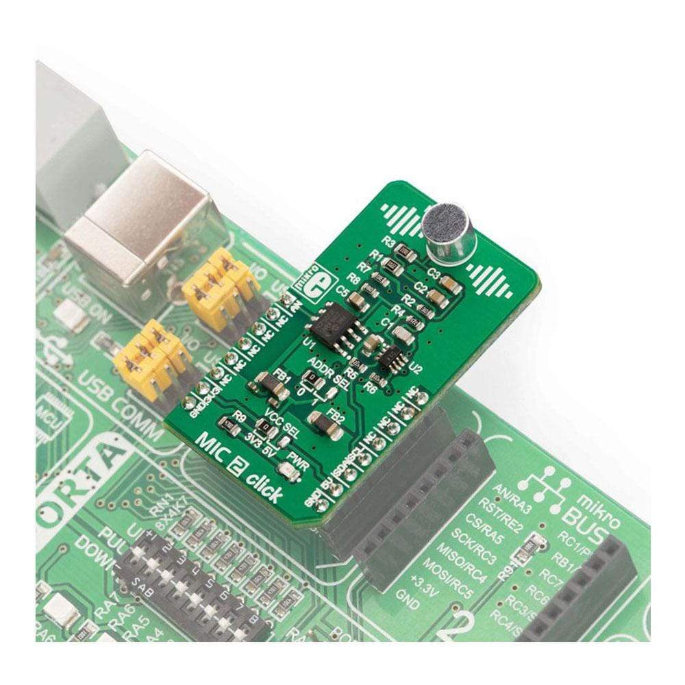
The MIC 2 Click Board™ is supported by a mikroSDK compliant library, which includes functions that simplify software development. This Click Board™ comes as a fully tested product, ready to be used on a system equipped with the mikroBUS™ socket.
Downloads
Das MIC 2 Click Board™ ist mit einem kleinen Elektretmikrofon und einer passenden Vorverstärkerschaltung ausgestattet. Das kleine Elektretmikrofon kann keinen ausreichenden Line-Pegel-Ausgang liefern; daher muss der Vorverstärker verwendet werden. Die Vorverstärkerschaltung besteht aus einem dualen Operationsverstärker und einem digital gesteuerten Potentiometer-IC. Dank des AD5171 ist es möglich, die Rückkopplungsschleifenverstärkung des MCP6022-Operationsverstärkers über die I2C-Schnittstelle in 64 diskreten Schritten zu steuern. Der digitale Potentiometer-IC AD5171 kann seinen Schleifkontakt mittels OTP-Sicherungsbit sperren: Nach der Sperrung behält er den programmierten Wert dauerhaft bei.
Das MIC 2 Click Board™ wird von einer mikroSDK-kompatiblen Bibliothek unterstützt, die Funktionen enthält, die die Softwareentwicklung vereinfachen. Dieses Click Board™ wird als vollständig getestetes Produkt geliefert und ist bereit für den Einsatz auf einem System, das mit der mikroBUS™-Buchse ausgestattet ist.
| General Information | |
|---|---|
Part Number (SKU) |
MIKROE-3445
|
Manufacturer |
|
| Physical and Mechanical | |
Weight |
0.019 kg
|
| Other | |
EAN |
8606018714926
|
Frequently Asked Questions
Have a Question?
Be the first to ask a question about this.