
Overview
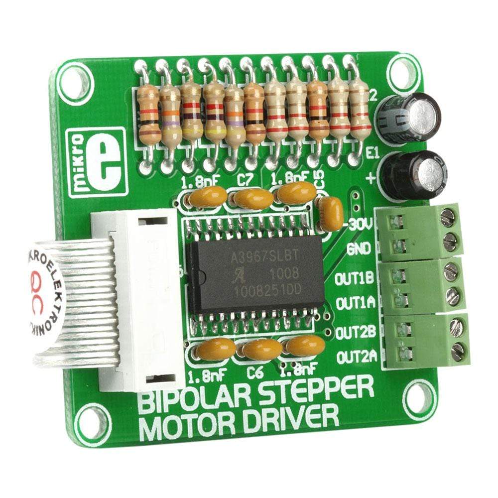
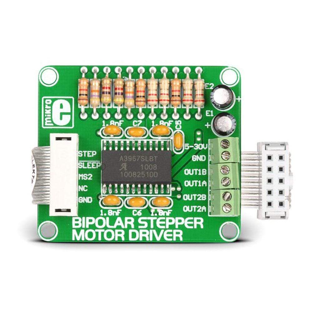
The Bipolar Stepper Motor Driver Board comes designed to let the user operate bipolar stepper motors in full-, half-, quarter-and eight-step modes. This additional board comes equipped with a complete microstepping motor driver with an in-built A3967SLB translator. The accessory board also includes a fixed off-time current regulator, which is capable of operating in slow, fast, or mixed current-decay mode. This current-decay control scheme not only increases step accuracy but also results in less power consumption and much reduced audible motor noise.
The Bipolar Stepper Motor Driver Board, which is available as a stand-alone device, can also be connected to the microcontroller. For establishing the connection of the Bipolar Stepper Motor Driver to the microcontroller on the development system, the user needs to use a flat cable with a regular IDC female connector. This female connector in turn should be connected to some development system.
Downloads
Die bipolare Schrittmotor-Treiberplatine ist so konzipiert, dass der Benutzer bipolare Schrittmotoren im Voll-, Halb-, Viertel- und Achtschrittmodus betreiben kann. Diese Zusatzplatine ist mit einem vollständigen Mikroschrittmotortreiber mit integriertem A3967SLB-Übersetzer ausgestattet. Die Zusatzplatine enthält außerdem einen Stromregler mit fester Ausschaltzeit, der im langsamen, schnellen oder gemischten Stromabfallmodus betrieben werden kann. Dieses Stromabfall-Steuerungsschema erhöht nicht nur die Schrittgenauigkeit, sondern führt auch zu einem geringeren Stromverbrauch und deutlich weniger hörbaren Motorgeräuschen.
Die als eigenständiges Gerät erhältliche Bipolar Stepper Motor Driver Board kann auch an den Mikrocontroller angeschlossen werden. Um die Verbindung des Bipolar Stepper Motor Driver mit dem Mikrocontroller auf dem Entwicklungssystem herzustellen, muss der Benutzer ein Flachbandkabel mit einer normalen IDC-Buchse verwenden. Diese Buchse muss wiederum an ein Entwicklungssystem angeschlossen werden.
| General Information | |
|---|---|
Part Number (SKU) |
MIKROE-334
|
Manufacturer |
|
| Physical and Mechanical | |
Weight |
0.015 kg
|
| Other | |
Warranty |
|
HS Code Customs Tariff code
|
|
EAN |
8606015070407
|
Frequently Asked Questions
Have a Question?
Be the first to ask a question about this.


