


Mikroelektronika d.o.o.
LDC1101 Click-Platine
LDC1101 Click-Platine
SKU: MIKROE-3240
Verfügbarkeit für Abholungen konnte nicht geladen werden
Key Features
Overview
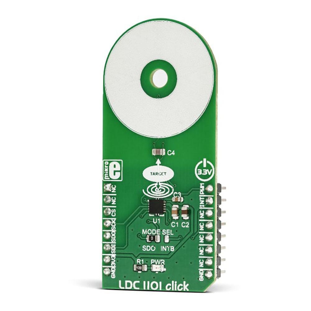
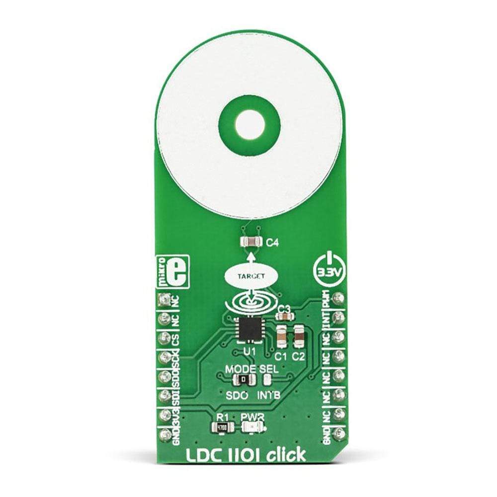
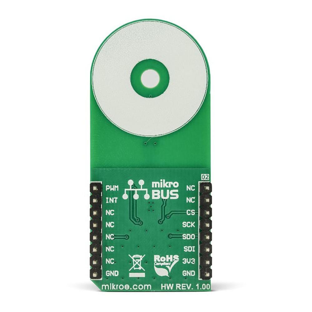
The LDC1101 Click Board™ is an inductance-to-digital converter It is designed for a range of different applications, based on inductive measurements. You can use it to detect the position, rotation, or motion of an object. LDC1101 carries the LDC1101, the integrated, high-resolution, high-speed, inductance-to-digital converter. The converter allows both the inductance and the impedance to be measured. The fast impedance + inductance (RP+L) mode offers separate 16-bit readings for both parameters, while the high-resolution inductance (LHR) mode offers a single reading with a resolution of 24 bits.
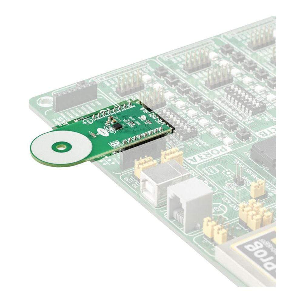
It comes in a package that also includes the mikroSDK software and a library with all the functions. The LDC1101 Click Board™ comes as a fully tested and approved prototype, making it a reliable device ready to use on the development board.
Downloads
Das LDC1101 Click Board™ ist ein Induktivität-Digital-Konverter. Es wurde für eine Reihe verschiedener Anwendungen entwickelt, die auf induktiven Messungen basieren. Sie können es verwenden, um die Position, Drehung oder Bewegung eines Objekts zu erkennen. LDC1101 enthält den LDC1101, den integrierten, hochauflösenden, schnellen Induktivität-Digital-Konverter. Der Konverter ermöglicht die Messung sowohl der Induktivität als auch der Impedanz. Der schnelle Impedanz- + Induktivitätsmodus (RP+L) bietet separate 16-Bit-Messwerte für beide Parameter, während der hochauflösende Induktivitätsmodus (LHR) einen einzelnen Messwert mit einer Auflösung von 24 Bit bietet.
Es wird in einem Paket geliefert, das auch die MikroSDK-Software und eine Bibliothek mit allen Funktionen enthält. Das LDC1101 Click Board™ wird als vollständig getesteter und zugelassener Prototyp geliefert und ist somit ein zuverlässiges Gerät, das sofort auf der Entwicklungsplatine verwendet werden kann.
| General Information | |
|---|---|
Part Number (SKU) |
MIKROE-3240
|
Manufacturer |
|
| Physical and Mechanical | |
Weight |
0.019 kg
|
| Other | |
EAN |
8606018713882
|
Frequently Asked Questions
Have a Question?
Be the first to ask a question about this.