


Mikroelektronika d.o.o.
SwipeSwitch Click-Platine
SwipeSwitch Click-Platine
SKU: MIKROE-3202
Verfügbarkeit für Abholungen konnte nicht geladen werden
Overview
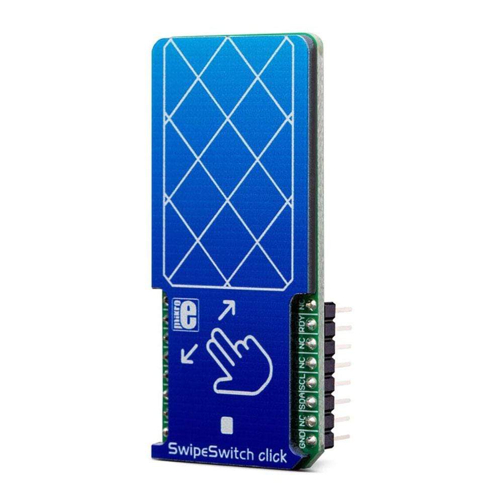
The SwipeSwitch Click Board™ is capacitive touch, gesture, and proximity sensing Click Board™, which is equipped with the IQS266, an integrated trackpad controller circuit which features ProxSense' and IQ Switch' technologies. This IC consists of a 2x3-channel capacitive trackpad controller, and a single self-capacitive proximity sensor, which can be used to wake up the device. This ensures very low power consumption, as the device is able to stay in the Sleep mode when not used. The IQS266 can detect a number of various configurable swipe and tap gestures. An Automatic Tuning Implementation (ATI) feature ensures an optimised performance in various conditions.
Downloads
Das SwipeSwitch Click Board™ ist ein kapazitives Touch-, Gesten- und Näherungssensor-Click Board™, das mit dem IQS266 ausgestattet ist, einem integrierten Trackpad-Controller-Schaltkreis mit den Technologien „ProxSense“ und „IQ Switch“. Dieser IC besteht aus einem kapazitiven 2x3-Kanal-Trackpad-Controller und einem einzelnen selbstkapazitiven Näherungssensor, der zum Aufwecken des Geräts verwendet werden kann. Dies gewährleistet einen sehr geringen Stromverbrauch, da das Gerät bei Nichtgebrauch im Ruhemodus bleiben kann. Das IQS266 kann eine Reihe verschiedener konfigurierbarer Wisch- und Tippbewegungen erkennen. Eine Automatic Tuning Implementation (ATI)-Funktion sorgt für eine optimierte Leistung unter verschiedenen Bedingungen.
| General Information | |
|---|---|
Part Number (SKU) |
MIKROE-3202
|
Manufacturer |
|
| Physical and Mechanical | |
Weight |
0.023 kg
|
| Other | |
EAN |
8606018715879
|
Frequently Asked Questions
Have a Question?
Be the first to ask a question about this.