


Mikroelektronika d.o.o.
Treiber-Click-Platine
Treiber-Click-Platine
SKU: MIKROE-3109
Verfügbarkeit für Abholungen konnte nicht geladen werden

Overview
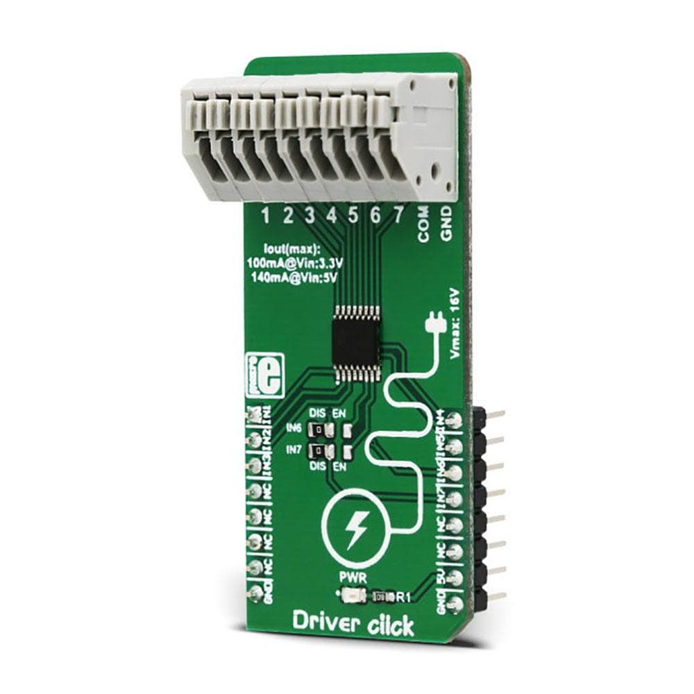
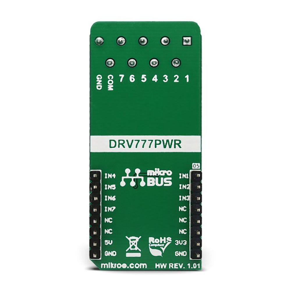
The Driver Click Board™ features an IC with seven integrated high-current sink drivers, which can be used to drive a wide range of loads via a simple parallel interface. These integrated drivers use high-efficiency MOSFETs for improved thermal performance. The DRV777 integrated motor and relay driver IC from Texas Instruments is the main active element of this Click Board™.
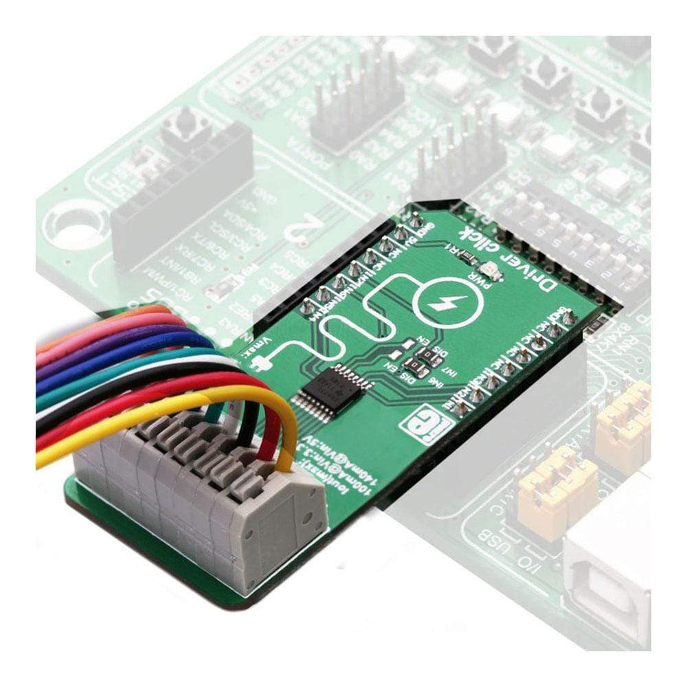
It is ideally suited for driving motors, relays, and similar inductive loads, as it features an internal free-wheeling diode for inductive kickback protection, on every channel. It operates with voltages up to 20 V, and by combining all the channels, it can sink up to 1A of current.
Downloads
Das Driver Click Board™ verfügt über einen IC mit sieben integrierten Hochstromsenkentreibern, mit denen eine Vielzahl von Lasten über eine einfache parallele Schnittstelle gesteuert werden kann. Diese integrierten Treiber verwenden hocheffiziente MOSFETs für eine verbesserte Wärmeleistung. Der integrierte Motor- und Relaistreiber-IC DRV777 von Texas Instruments ist das wichtigste aktive Element dieses Click Board™.
Es eignet sich ideal zum Antreiben von Motoren, Relais und ähnlichen induktiven Lasten, da es auf jedem Kanal über eine interne Freilaufdiode zum Schutz vor induktivem Rückschlag verfügt. Es arbeitet mit Spannungen bis zu 20 V und kann durch die Kombination aller Kanäle bis zu 1 A Strom aufnehmen.
| General Information | |
|---|---|
Part Number (SKU) |
MIKROE-3109
|
Manufacturer |
|
| Physical and Mechanical | |
Weight |
0.023 kg
|
| Other | |
EAN |
8606018713349
|
Frequently Asked Questions
Have a Question?
Be the first to ask a question about this.