


Mikroelektronika d.o.o.
LTE IoT Click-Platine
LTE IoT Click-Platine
SKU: MIKROE-3072
Verfügbarkeit für Abholungen konnte nicht geladen werden


Overview
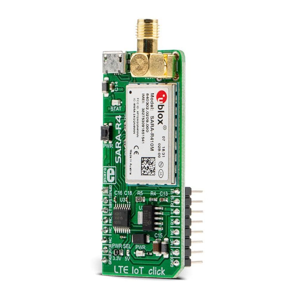
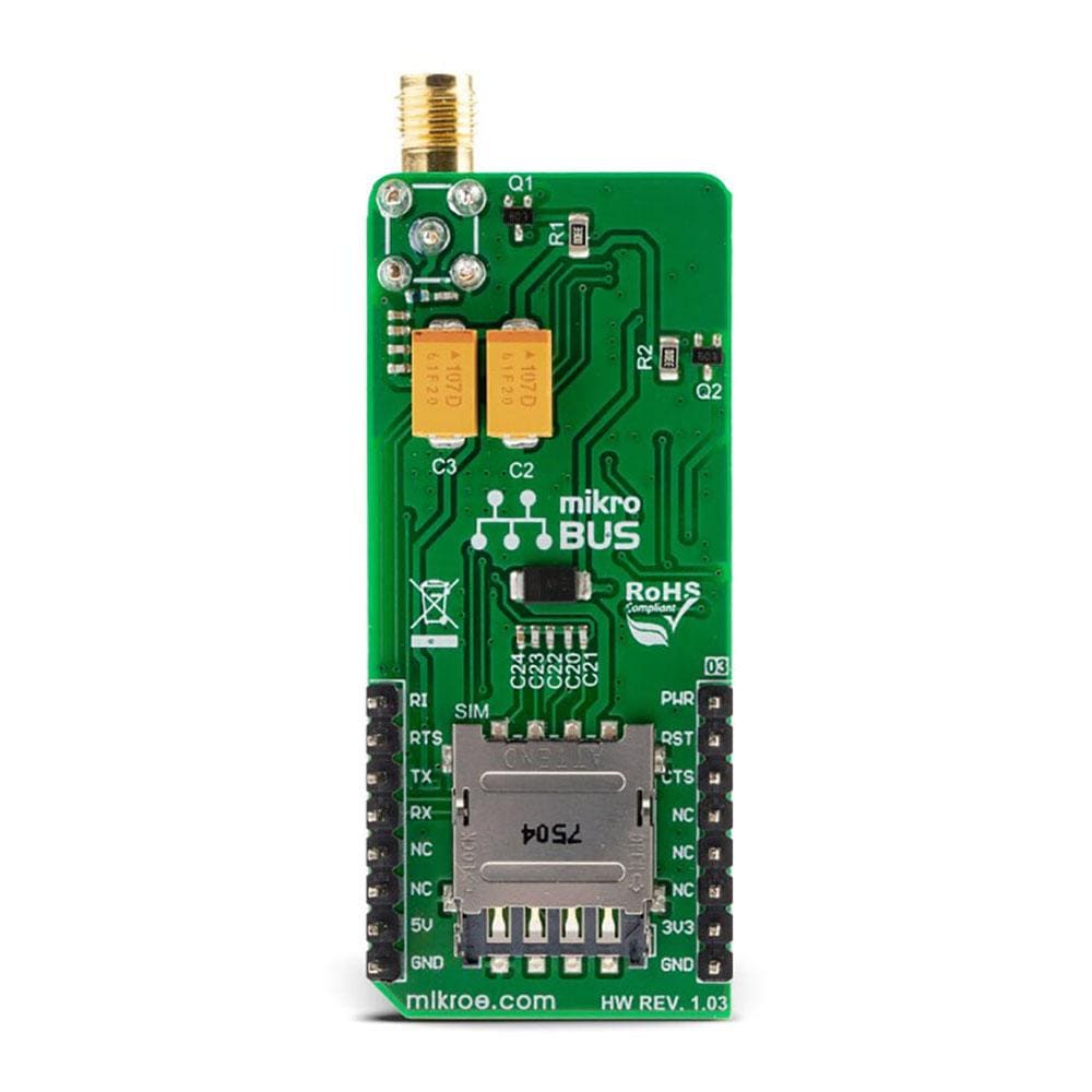
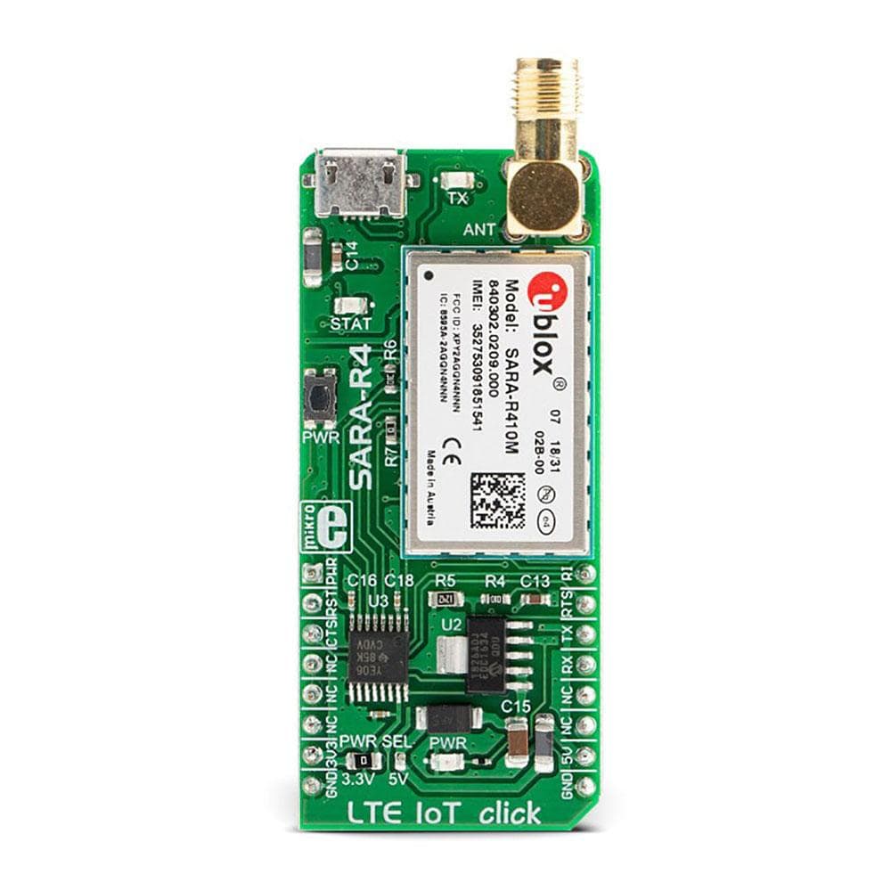
The LTE IoT Click Board™ is a compact add-on board that contains a complete and cost-efficient solution offering multi-band data transmissions for Low-Power Wide-Area solutions. This board features the SARA-R410M-02B, a cellular module that supports LTE CAT M1 and Narrowband 1 (NB1) technologies, developed with IoT applications in mind from u-Blox. Designed for worldwide operation with a rich set of Internet protocols, equipped with industry-standard interfaces (UART, USB…), Network and Status indicators, familiar AT commands set over the UART interface, micro USB connector for interfacing with software application from u-Blox, are just some of the features available on this Click Board™. Its many features make it suitable for use in a wide range of M2M applications, such as smart metering in various industries (agriculture, gas distribution, water distribution), product tracking, and more.
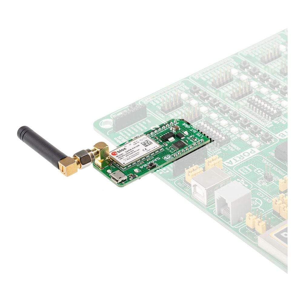
The LTE IoT Click is supported by a mikroSDK compliant library, which includes functions that simplify software development. This Click Board™ comes as a fully tested product, ready to be used on a system equipped with the mikroBUS™ socket.
Downloads
Das LTE IoT Click Board™ ist eine kompakte Zusatzplatine, die eine vollständige und kostengünstige Lösung enthält, die Multiband-Datenübertragungen für Low-Power-Wide-Area-Lösungen bietet. Diese Platine verfügt über das SARA-R410M-02B, ein Mobilfunkmodul, das LTE CAT M1- und Narrowband 1 (NB1)-Technologien unterstützt und für IoT-Anwendungen von u-Blox entwickelt wurde. Entwickelt für den weltweiten Betrieb mit einer Vielzahl von Internetprotokollen, ausgestattet mit Industriestandardschnittstellen (UART, USB...), Netzwerk- und Statusanzeigen, vertrauten AT-Befehlen über die UART-Schnittstelle, Micro-USB-Anschluss für die Schnittstelle mit Softwareanwendungen von u-Blox, sind nur einige der auf diesem Click Board™ verfügbaren Funktionen. Seine vielen Funktionen machen es für den Einsatz in einer Vielzahl von M2M-Anwendungen geeignet, wie z. B. intelligente Messung in verschiedenen Branchen (Landwirtschaft, Gasversorgung, Wasserversorgung), Produktverfolgung und mehr.
Das LTE IoT Click wird von einer mikroSDK-kompatiblen Bibliothek unterstützt, die Funktionen enthält, die die Softwareentwicklung vereinfachen. Dieses Click Board™ wird als vollständig getestetes Produkt geliefert und ist bereit für den Einsatz auf einem System, das mit der mikroBUS™-Buchse ausgestattet ist.
| General Information | |
|---|---|
Part Number (SKU) |
MIKROE-3072
|
Manufacturer |
|
| Physical and Mechanical | |
Weight |
0.031 kg
|
| Other | |
EAN |
8606018713547
|
Frequently Asked Questions
Have a Question?
Be the first to ask a question about this.