


Mikroelektronika d.o.o.
4D-Display Click Board™
4D-Display Click Board™
SKU: MIKROE-3044
Verfügbarkeit für Abholungen konnte nicht geladen werden

Overview
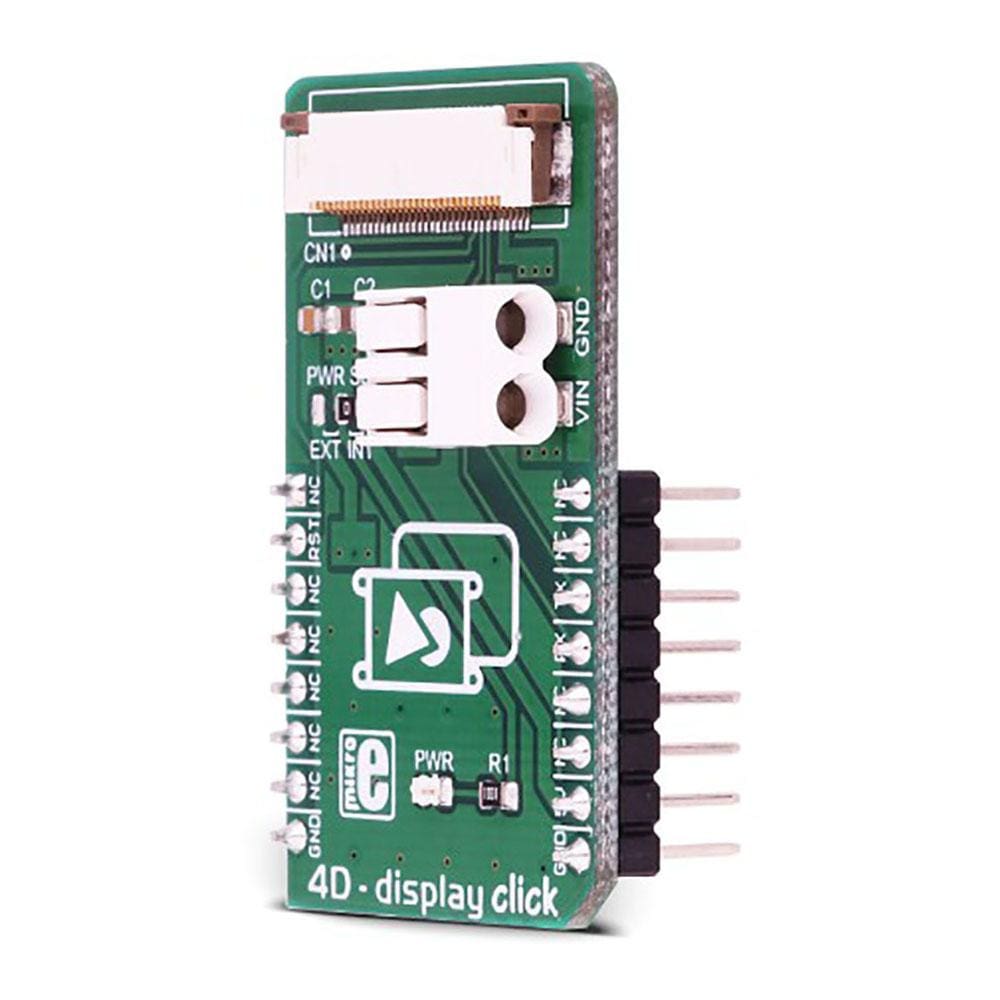
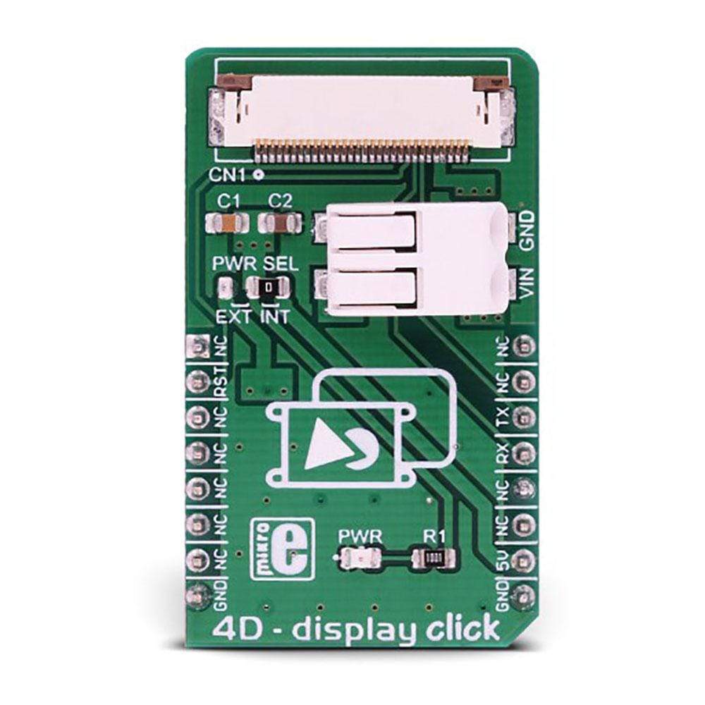
The 4D - Display Click Board™ is an adapter Click Board™ that offers a mikroBUS interface for controlling 4D Systems gen4 Series intelligent Display Modules. 4D Systems designs and manufactures a wide range of Intelligent Display Modules equipped with powerful graphics processors. Their displays allow graphical objects control by exchanging specifically formatted messages with the external microcontroller (MCU) over the UART.
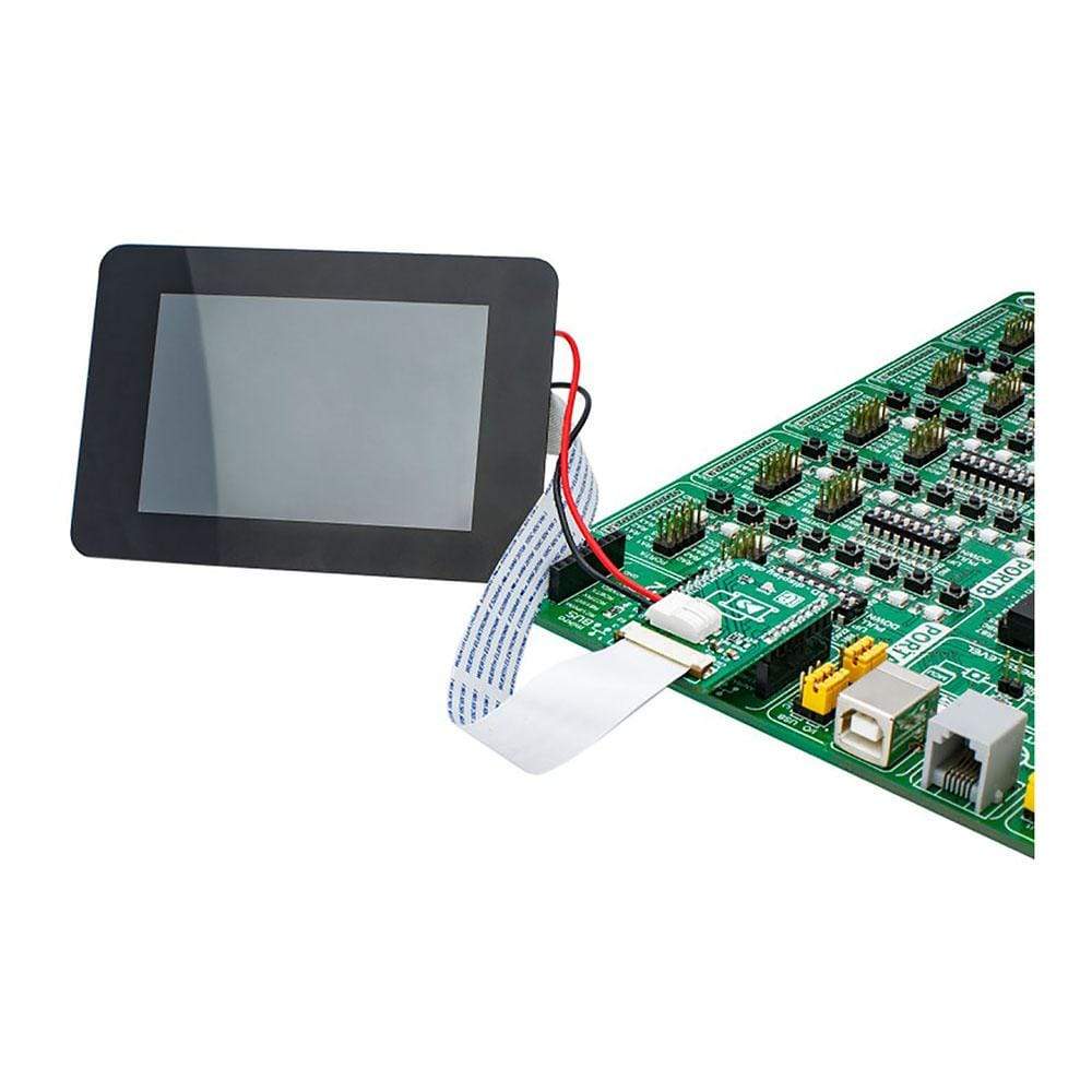
By utilizing the 4D - Display Click Board™, it is possible to develop an MCU firmware application that can interact with the graphic objects on the 4D Intelligent Display Module over the mikroBUS. This significantly simplifies the application design, while reducing the processing load on the host MCU, allowing amazing graphically based applications to be created, even with slower 8-bit MCUs.
Downloads
Das 4D - Display Click Board™ ist ein Adapter Click Board™, das eine MikroBUS-Schnittstelle zur Steuerung intelligenter Anzeigemodule der Serie gen4 von 4D Systems bietet. 4D Systems entwickelt und fertigt eine breite Palette intelligenter Anzeigemodule mit leistungsstarken Grafikprozessoren. Ihre Anzeigen ermöglichen die Steuerung grafischer Objekte durch den Austausch speziell formatierter Nachrichten mit dem externen Mikrocontroller (MCU) über den UART.
Mithilfe des 4D - Display Click Board™ ist es möglich, eine MCU-Firmware-Anwendung zu entwickeln, die über den Mikrobus mit den Grafikobjekten auf dem 4D Intelligent Display Module interagieren kann. Dies vereinfacht das Anwendungsdesign erheblich und reduziert gleichzeitig die Verarbeitungslast auf der Host-MCU. So können selbst mit langsameren 8-Bit-MCUs erstaunliche grafikbasierte Anwendungen erstellt werden.
| General Information | |
|---|---|
Part Number (SKU) |
MIKROE-3044
|
Manufacturer |
|
| Physical and Mechanical | |
Weight |
0.019 kg
|
| Other | |
EAN |
8606018713080
|
Frequently Asked Questions
Have a Question?
Be the first to ask a question about this.