Zu Produktinformationen springen
1 von 4

Mikroelektronika d.o.o.

Cap Touch 2 Click-Platine

Cap Touch 2 Click-Platine

SKU: MIKROE-2964
Normaler Preis
£12.60 GBP ohne MwSt
Normaler Preis £18.00 GBP Verkaufspreis
£12.60 GBP ohne MwSt
Sale Ausverkauft
Versand wird beim Checkout berechnet
If no stock shown above, check availability
Vollständige Details anzeigen
} ] }

Overview

Das Cap Touch 2 Click Board™ ist ein kapazitives Touch-Sensing Click Board™ mit dem CAP1166, einem fortschrittlichen Touch-/Näherungssensor-IC, der mit einer Reihe verschiedener Touch-/Näherungsfunktionen ausgestattet ist und die Entwicklung robuster und ästhetisch ansprechender Touch-Schnittstellen ermöglicht. Neben sechs berührungsempfindlichen Kanälen verfügt der Sensor-IC über sechs unabhängige LED-Treiber mit mehreren Betriebsmodi, einschließlich Touch-Sensor-Verknüpfung sowie Puls- und Atemeffekten.

Es unterstützt außerdem die Erkennung mehrerer Berührungsmuster (MTPD) und eine Drücken-und-Halten-Funktion. Kapazitive Berührungssensoreingänge sind vor Fehlerkennung geschützt, die durch geringes Rauschen und HF-Interferenzen verursacht werden kann, und bieten eine sehr zuverlässige Berührungssensorfunktion.

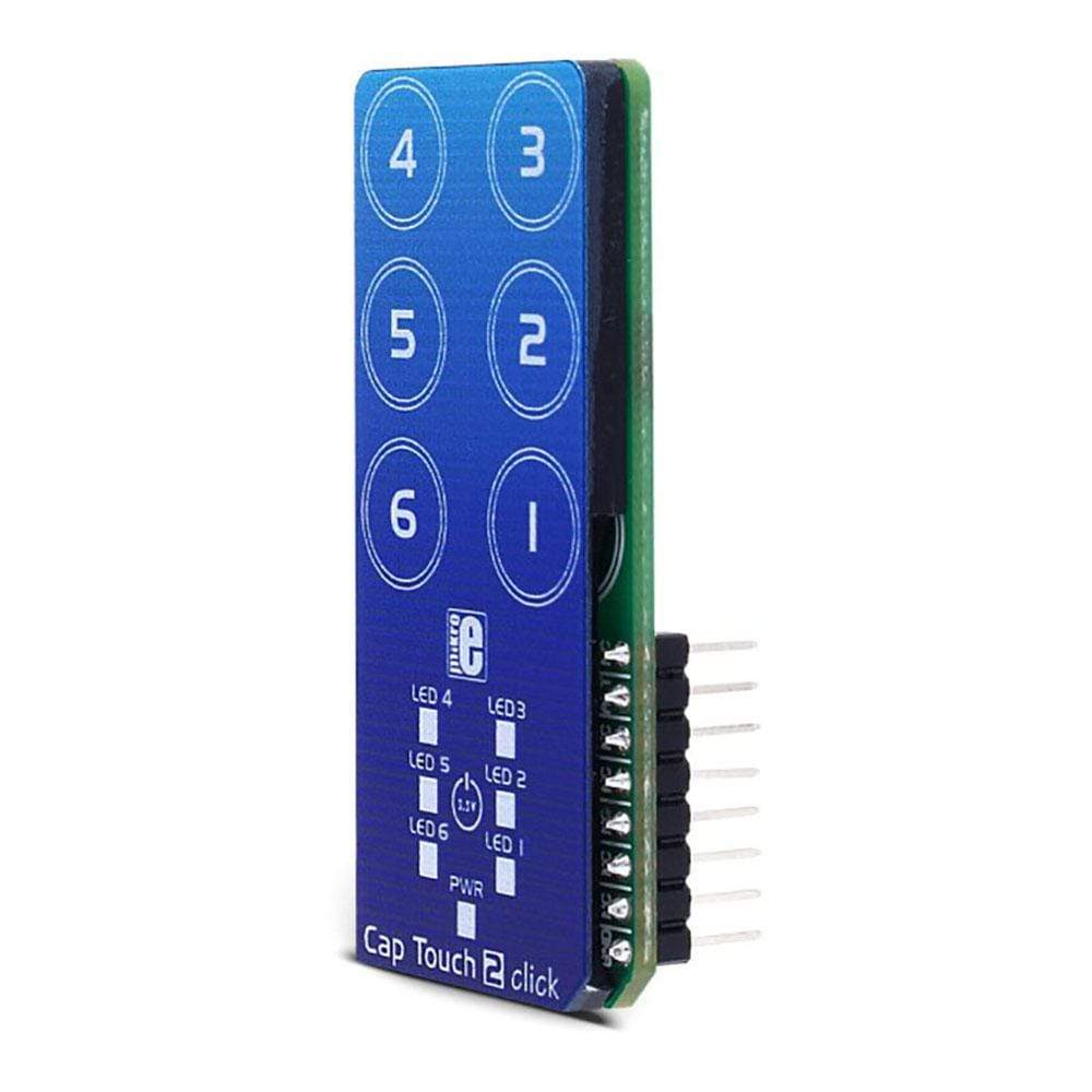
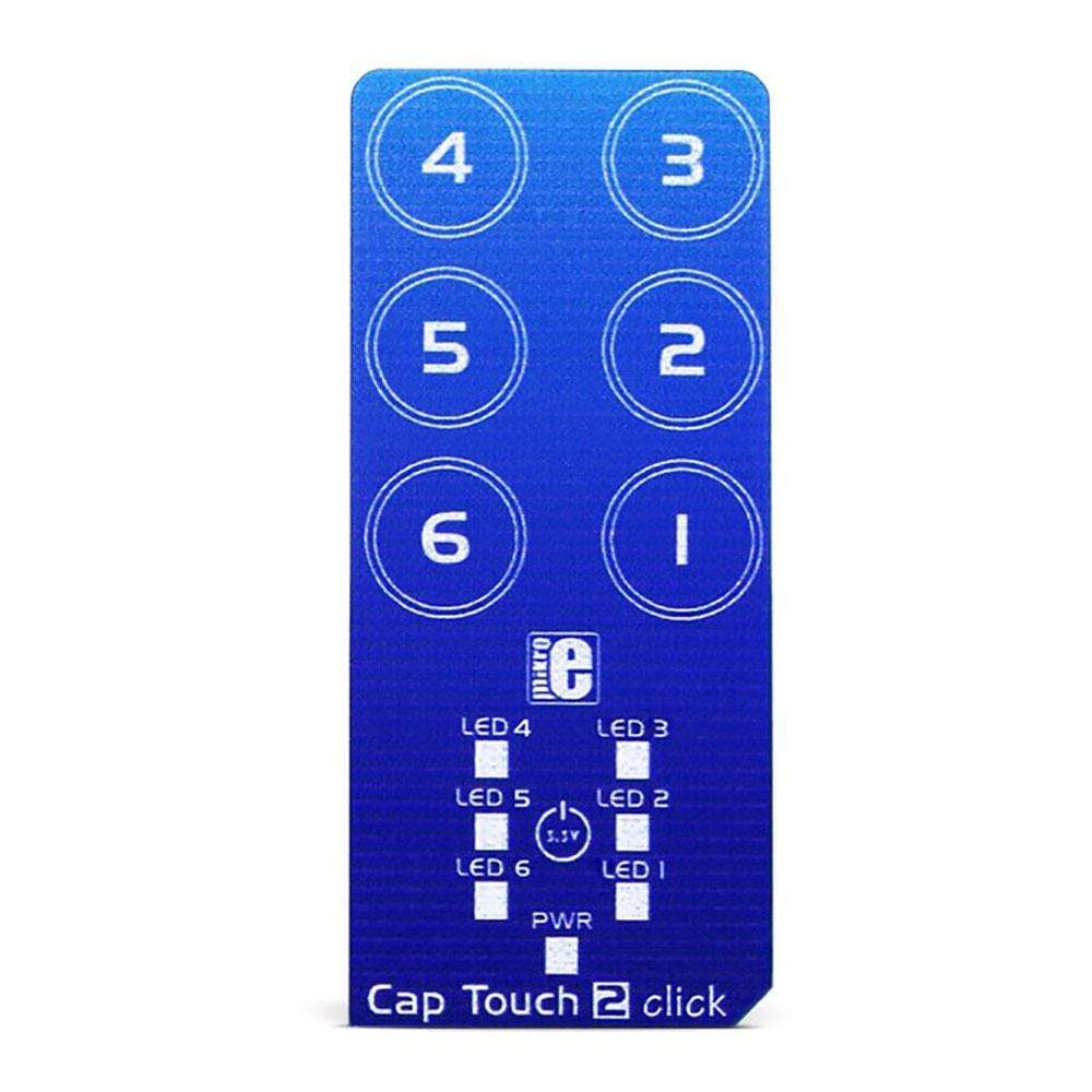
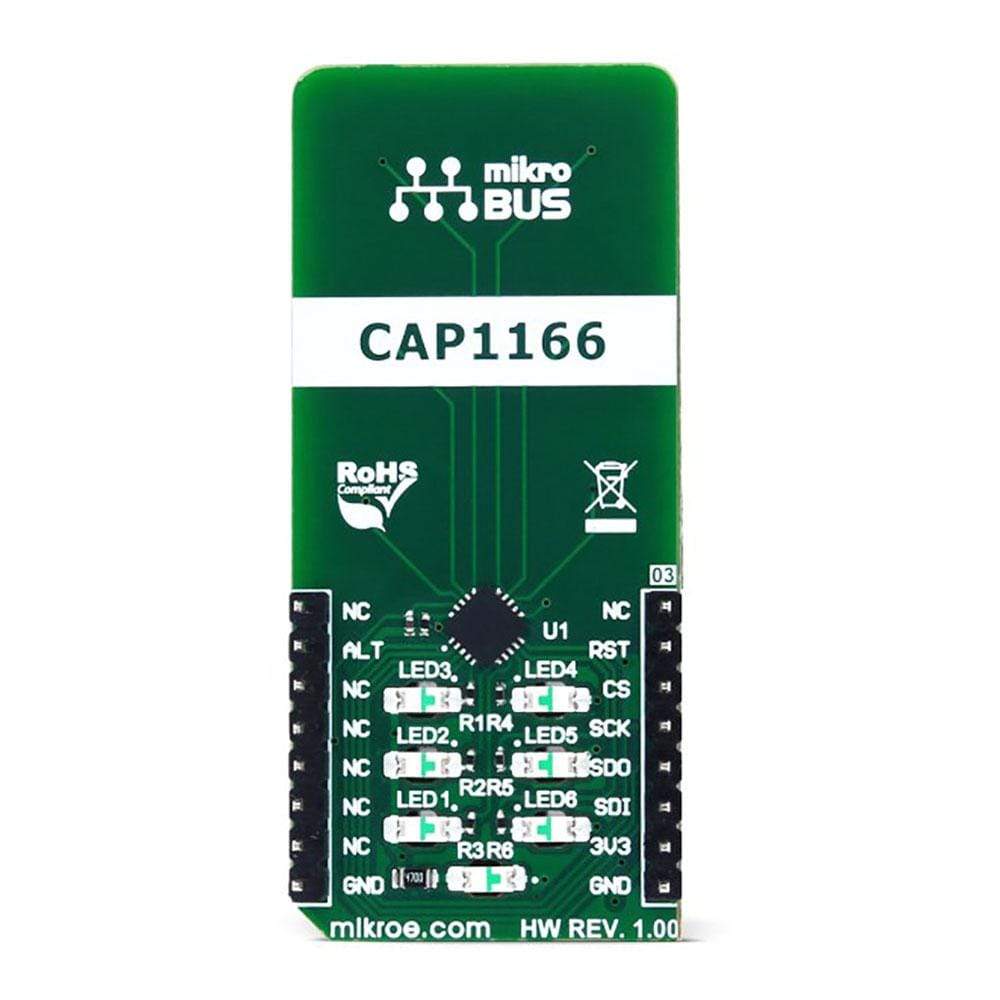
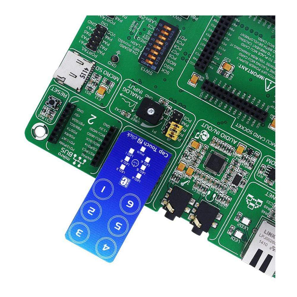
The Cap Touch 2 Click Board™ is a capacitive touch sensing Click board™ which features the CAP1166, an advanced touch/proximity sensor IC, packed with a range of different touch/proximity functionalities, allowing development of robust and aesthetically pleasing touch interfaces. Besides six touch sensitive channels, the sensor IC has six independent LED drivers, with several operating modes, including touch sensor linking, as well as the pulsing and breathing effects. It also supports Multiple Touch Pattern Detection (MTPD), and press-and-hold function. Capacitive touch sensor inputs are protected from false detections, which can be caused by the low noise and RF interferences, providing a very reliable touch sensing functionality.

Due to advanced capacitive touch proximity functions and technologies that allow reliable sensing, Cap Touch 2 click offers very reliable and accurate sensing for any application that uses capacitive touch sensing functions, such as desktop or notebook computers, LCD/TFT monitors, various types of consumer electronics, home appliances, and other applications that can benefit of having an appealing, reliable and feature-rich touch activated user interface.

How Does The Cap Touch 2 Click Board™ Work?

The capacitive sensor IC used on the Cap Touch 2 Click Board™ is the CAP1166, a 6 channel capacitive touch sensor with 6 LED drivers, from Microchip. This IC is composed of six input capacitive touch channels, implemented with the RightTouch® technology, six LED drives with programmable signaling functions, and the logic section, which uses the standard SPI communication interface. Besides the SPI bus, the logic section uses few more lines - for the device reset and for triggering the alert (interrupt) event.
MikroElektronikas Cap Touch 2 click

The Cap Touch 2 Click Board™ itself has six PCB pads, used to sense touch or proximity events. These pads are the only elements on the top of the board, allowing installation of the protective acrylic glass layer. These pads can be programmed to generate a touch event for both when they are pressed, and when they are released. The capacitive sensor channels feature programmable sensitivity and an automatic recalibration, used to compensate for environmental changes. The recalibration procedure can be triggered either automatically, or on-demand, and it is used to set the base register value for the "not touched" state of the input channel. The enabled input channels are polled in a cyclic order and if the difference between the base value and the measured value on a particular channel is over the threshold, a touch event will be generated.

The CAP1166 IC also integrates sections that provide an efficient interference protection. The EMI and RFI detection sections provide protection by discarding the corrupted bytes if the detected noise threshold is exceeded. Also, false input readings, such as the negative values and "stuck button" events are handled by the internal algorithms, which will set the respective bits to indicate the problem, and can be set to trigger a recalibration procedure.

There are three power modes of operation:

  • Fully Active mode, which monitors all the input channels and all the LED drivers are active. Registers are available for both reading and writing.
  • Stand-by mode, which will monitor only the selected channels. The selected channels will be able to trigger interrupts. Communication will be still functional and the device can be set to a Fully Active mode. This mode uses less power than the Fully Active mode.
  • Deep Sleep mode, which consumes the least power. In this mode, all the input channels and LED drivers are disabled. The communication is possible only when the CAP1166 IC is targeted by the host MCU.

Multiple touch pattern detection (MTPD) is used to set the pattern which will generate a touch event. This pattern may consist of multiple specific sensors touched at once, a minimal number of touched sensors, or when their noise flag bit is set in the status register. This function can be used to detect a closed lid or similar event.

The Cap Touch 2 Click Board™ contains six LEDs, mounted on the back side of the PCB, inside the specially designed openings. These LEDs can be linked to the corresponding sensing channel or can be controlled by the host MCU. As described above, these LEDs can be programmed to indicate a touch event with a range of lighting effects, including breathing, two modes of pulsing with the programmable parameters, and an ON-OFF state.

The interrupt engine allows to differentiate between the simple touch, and touch and hold events. The interrupt can be generated once when a pad touch is detected, or it can be repeatedly generated while the pad is touched. The programmable timer is started after the first touch event on a specific channel, and if no release event is detected after the timer expires, the interrupt is generated, in the programmed intervals. This function is very useful for building volume up/down buttons, light dimming buttons, and similar applications. The interrupt event will also drive the /ALERT pin to a state, defined in the respective configuration register. This pin is routed to the mikroBUS™ INT pin and it is used to trigger an interrupt event on the host MCU.

The RST pin is routed to the RST pin of the mikroBUS™ and it is used to reset the CAP1166 IC. To reset the device, this pin has to be set to a HIGH logic level. This will clear all the readings and reset the configuration registers to their factory default values. The device will be kept in a Deep Sleep mode until this pin is set to a LOW logic level. This pin is equipped with a pull-down resistor.

More information about the registers and their functions can be found in the CAP1166 IC datasheet. However, the provided click library offers a function for easy and simple control of the Cap Touch 2 Click Board™. The provided application example demonstrates their functionality and it can be used as a reference for custom projects.

SPECIFICATIONS

Type Capacitive
Applications The Cap Touch 2 Click Board™ can be used for desktop or notebook computers control, LCD/TFT monitors, various types of consumer electronic, home appliances, and other applications that can benefit of having a reliable and feature-rich touch activated user interface.
On-board modules CAP1166, a 6 channel capacitive touch sensor with 6 LED drivers, from Microchip
Key Features Reliable capacitive touch detection technology, noise filtering, six input channels, six programmable LED drivers, press and hold function, automatic recalibration and programmable sensitivity for each channel, etc.
Interface SPI
Compatibility mikroBUS
Click board size L (57.15 x 25.4 mm)
Input Voltage 3.3V

PINOUT DIAGRAM

This table shows how the pinout of the Cap Touch 2 Click Board™ corresponds to the pinout on the mikroBUS™ socket (the latter shown in the two middle columns).

Notes Pin Mikrobus logo.png Pin Notes
NC 1 AN PWM 16 NC
Device Reset RST 2 RST INT 15 ALT Alert/Interrupt
SPI Chip Select CS 3 CS RX 14 NC
SPI Clock SCK 4 SCK TX 13 NC
SPI Master In SDO 5 MISO SCL 12 NC
SPI Master Out SDI 6 MOSI SDA 11 NC
Power Supply +3.3V 7 3.3V 5V 10 NC
Ground GND 8 GND GND 9 GND Ground

ONBOARD SETTINGS AND INDICATORS

Label Name Default Description
LD1 - LD6 LED1 - LED6 - Programmable touch LED indicators
LD7 PWR - Power LED Indicator


Frequently Asked Questions

Have a Question?

Be the first to ask a question about this.

Ask a Question

Customer Reviews

Be the first to write a review
0%
(0)
0%
(0)
0%
(0)
0%
(0)
0%
(0)