


Mikroelektronika d.o.o.
UT-S 7-Segment R Click-Platine
UT-S 7-Segment R Click-Platine
SKU: MIKROE-2840
Verfügbarkeit für Abholungen konnte nicht geladen werden
Overview
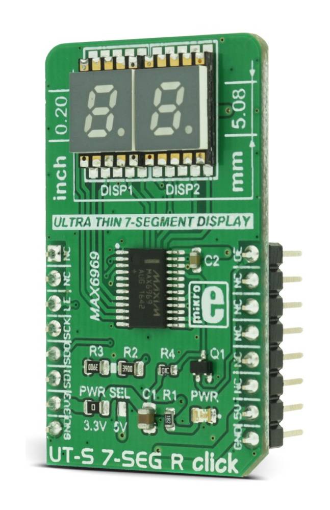
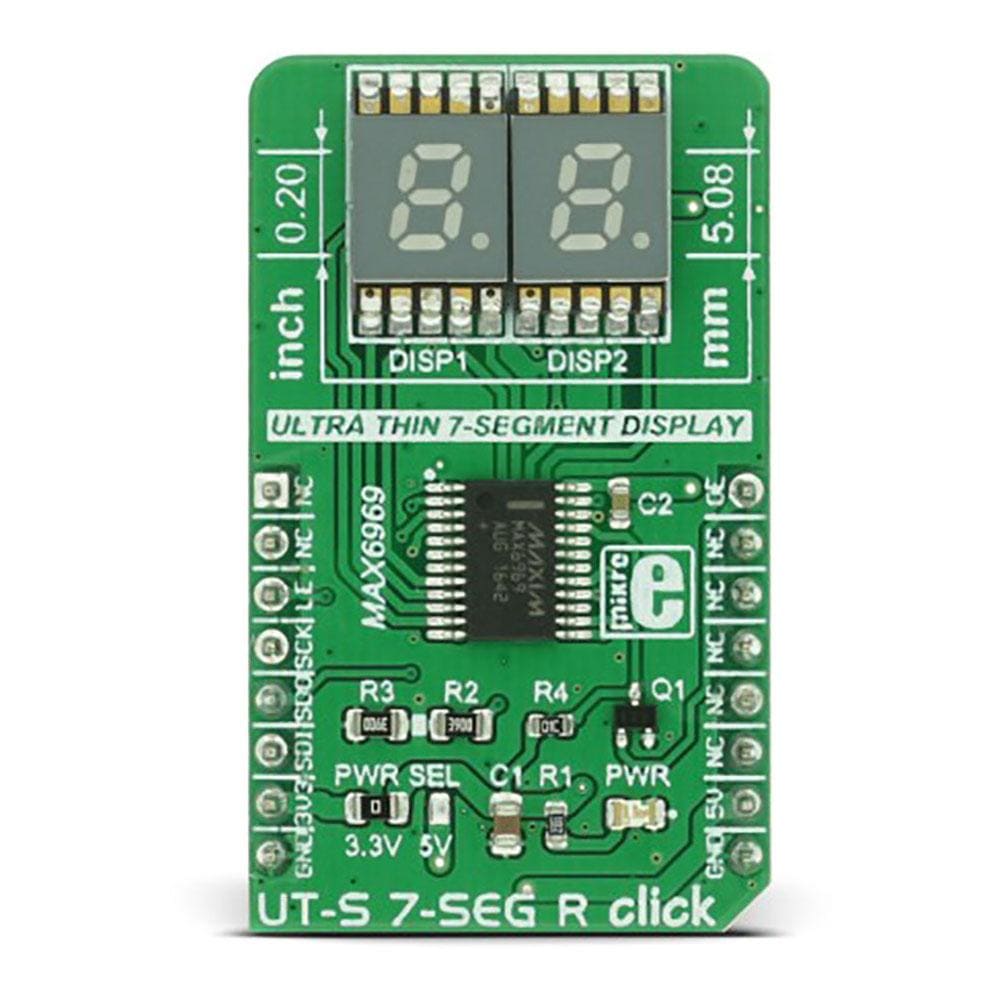
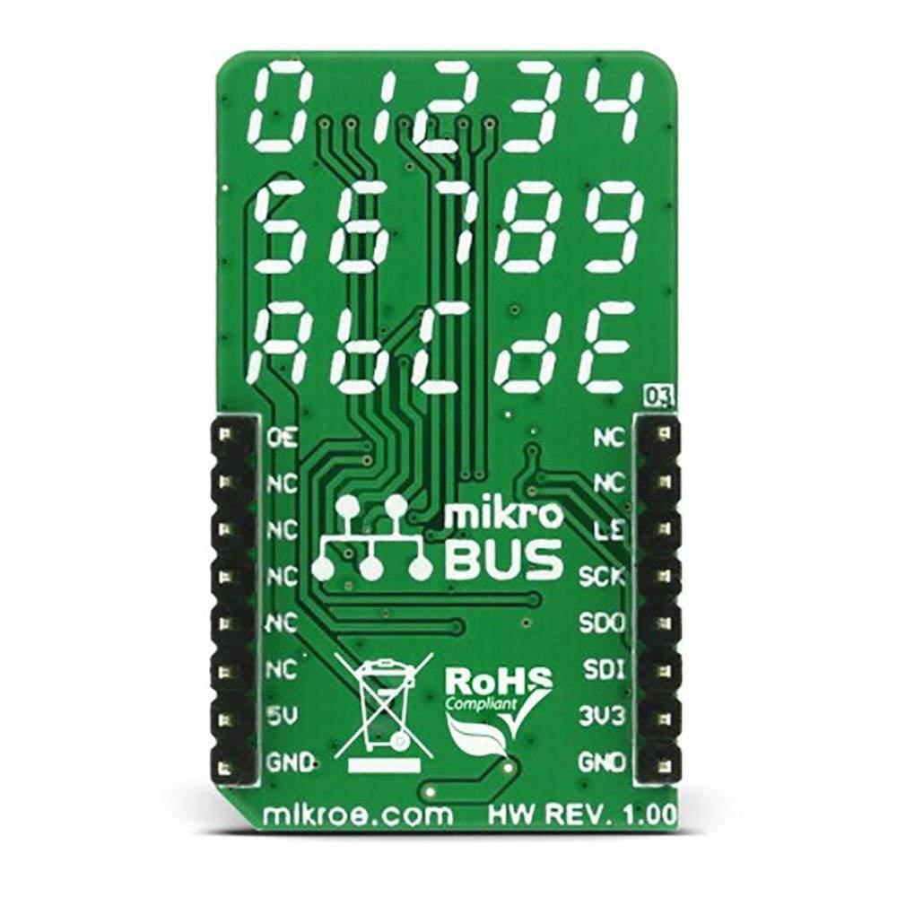
The UT-S 7 Seg R Click Board™ uses two SMD ultra-thin DSM7UA20101 7-SEG LED displays, made with the patented technology that delivers a thickness of only 2.1 mm. These displays are driven by the MAX6969, a constant current LED integrated driver from Maxim Integrated, which uses the SPI serial interface for communication and delivers a steady and constant power source for the LED segments.
7-segment LED display is the most commonly used type of display to represent changing numerical values. The principle is very simple - seven LED segments are positioned in a certain shape and by turning specific segments on or off, the shape that resembles a specific number is lit. This method of displaying numbers was first used in the beginning of the 20th century, but after the invention of the LED in ‘70, it is the most commonly used method to display numbers. It utilizes a fairly simple and cheap design with the numbers clearly visible. Be it a clock on the nightstand, a billboard at the airport, a gauge on some machine, a panel on some instrument or a display on the pump at the gas station - the numbers will be always easy to see and read, even in the dark.
Downloads
Das UT-S 7 Seg R Click Board™ verwendet zwei ultradünne SMD DSM7UA20101 7-SEG-LED-Displays, die mit der patentierten Technologie hergestellt werden, die eine Dicke von nur 2,1 mm ermöglicht. Diese Displays werden vom MAX6969 angetrieben, einem integrierten LED-Treiber mit konstantem Strom von Maxim Integrated, der die serielle SPI-Schnittstelle zur Kommunikation verwendet und eine stabile und konstante Stromquelle für die LED-Segmente liefert.
Die 7-Segment-LED-Anzeige ist die am häufigsten verwendete Anzeigeart zur Darstellung sich ändernder numerischer Werte. Das Prinzip ist sehr einfach: Sieben LED-Segmente sind in einer bestimmten Form angeordnet und durch Ein- oder Ausschalten bestimmter Segmente leuchtet die Form, die einer bestimmten Zahl ähnelt. Diese Methode zur Anzeige von Zahlen wurde erstmals zu Beginn des 20. Jahrhunderts verwendet, ist aber nach der Erfindung der LED im Jahr 1970 die am häufigsten verwendete Methode zur Anzeige von Zahlen. Dabei wird ein ziemlich einfaches und kostengünstiges Design verwendet, bei dem die Zahlen deutlich sichtbar sind. Ob es sich um eine Uhr auf dem Nachttisch, eine Werbetafel am Flughafen, eine Anzeige an einer Maschine, eine Tafel an einem Instrument oder eine Anzeige an der Zapfsäule an der Tankstelle handelt – die Zahlen sind immer gut zu sehen und zu lesen, auch im Dunkeln.
| General Information | |
|---|---|
Part Number (SKU) |
MIKROE-2840
|
Manufacturer |
|
| Physical and Mechanical | |
Weight |
0.02 kg
|
| Other | |
EAN |
8606018712052
|
Frequently Asked Questions
Have a Question?
Be the first to ask a question about this.