Ozone 2 Click Board
Ozone 2 Click Board
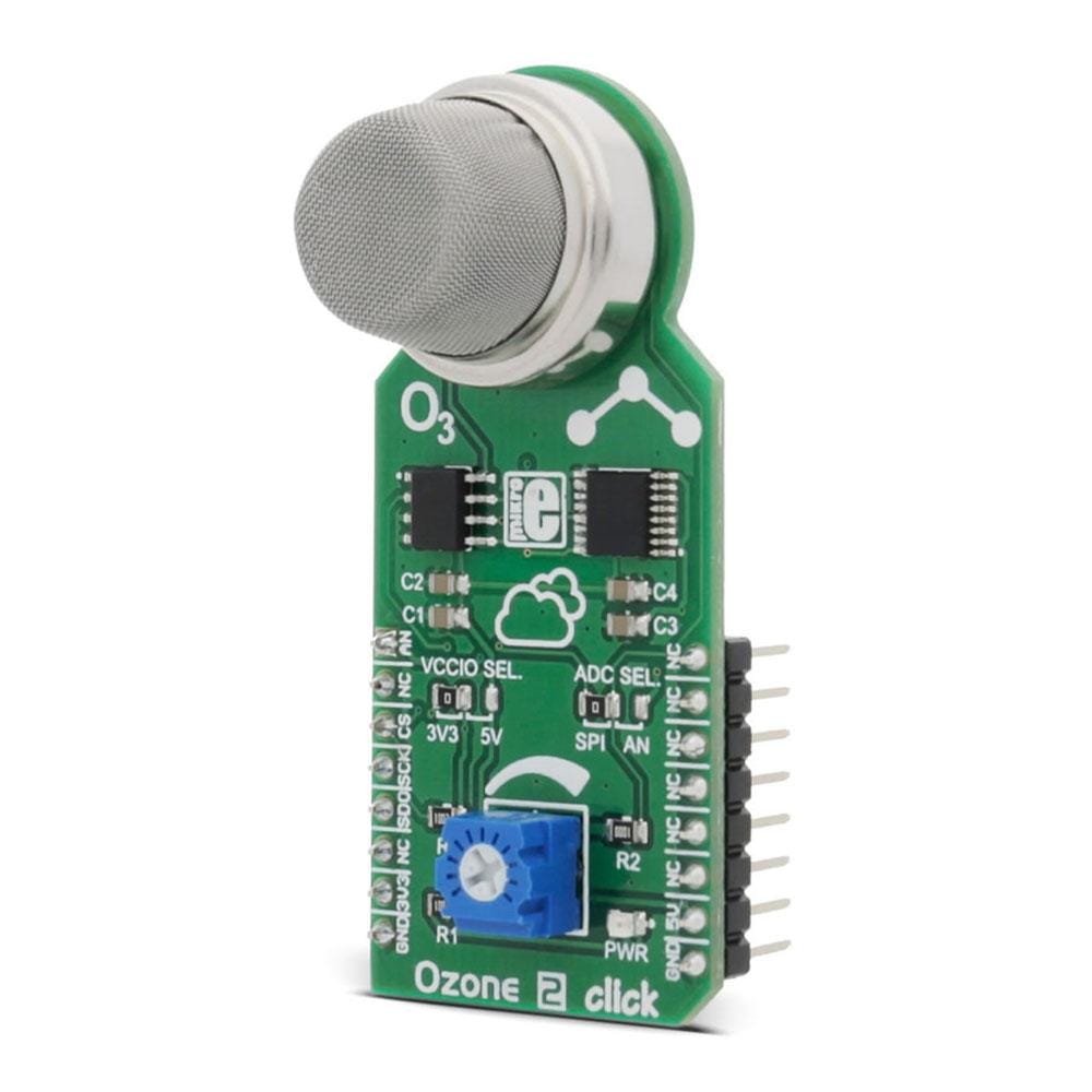
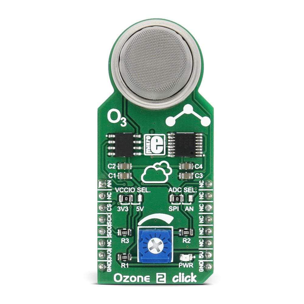
Das Ozone 2 Click Board™ basiert auf dem Winsen MQ131-Sensor für Ozon (O3). Der Sensor gibt eine analoge Spannung aus, die vom integrierten 22-Bit-ADC-Wandler MCP3551 umgewandelt oder über den AN-Pin auf dem MikroBUS an den Mikrocontroller gesendet wird, je nach Position des ADC SEL.-Jumpers.
Das Ozone 2 Click Board™ ist für den Betrieb mit 5 V-Stromversorgung ausgelegt. Es kommuniziert mit dem Zielmikrocontroller über die SPI-Schnittstelle oder einen AN-Pin auf der MikroBUS-Leitung.
Featuring an accurate 22-bit ADC and a high-quality O3 sensor protected by a stainless mesh, the Ozone 2 Click Board™ can be used in a range of applications used to measure or detect O3 gas concentrations in the atmosphere, for small testing equipment development, various warning systems for air quality / ozone pollution, and other similar applications that are used for the ozone concentration detection and monitoring.
How Does The Ozone 2 Click Board™ Work?
The main sensor component of the Ozone 2 Click Board™ is the MQ131 ozone (O3) gas sensor from Winsen Sensor, which uses the SnO2 (tin-oxide) alloy, which decreases its resistance while exposed to the O3 gas. The greater the O3 concentration is, the more conductive this material becomes. This can be utilized to obtain the O3 concentration readings. The sensor itself contains a small heating element, connected to 5V power supply. It needs to be preheated for 48h before it can perform as specified. The sensitivity of the sensor is given as the ratio between the resistance in air and the resistance in the O3 gas concentration of 50ppm, which is ≥ 3 (RO/RS ≥ 3). The sensor is protected against particles and mechanical damage by a stainless mesh, however, exposing to excessive moisture and corrosive gases can damage the inner structure.
The measuring circuit consists of the MQ131 sensor, a power source and a load resistor (RL) between the output pin and GND. The sensor with its internal resistance forms a voltage divider with the load resistor. The RL is designed as a variable resistor, allowing the output voltage to be trimmed to the desired value. The calibration should be performed in controlled conditions, as the resistance of the sensor is affected by both the ambient temperature and humidity. The sensor can be used to measure relative O3 concentration change without an accurate calibrating, which is useful for building applications that can be used as warning systems. The middle tap of the sensor-RL voltage divider is routed to an SMD jumper labelled as ADC SEL. This jumper can be used to redirect the measuring voltage either to the ADC for sampling or to the AN pin, so it can be used in an external circuitry (external ADC or some other form of measurement signal conditioning).
The MCP3551, a 22bit sigma-delta ADC from Microchip is used to sample the output of the sensor when selected by the ADC SEL jumper. This ADC converts the input voltage with a very high resolution of 22 bits and low noise, to a digital data, which can be obtained via the SPI interface of the Ozone 2 Click Board™. This ADC uses the reference voltage which is the same as the power supply voltage, and in this case, it is powered by 5V from the mikroBUS™ power rail. The reference voltage is used to calculate the value of the input voltage based on data received from the SPI bus, by using the following formula:
VSENS = DATA x VREF / FS
VREF is the same as the power supply for this circuit, which means VREF = 5V, and the highest number written with 22 bits (FS) is 4,194,303. DATA is the 22-bit conversion value.
As already mentioned, the ADC uses a 5V power supply. Therefore, this board needs a level conversion circuitry in order to be interfaced with 3.3V MCUs. This Click board™ uses the TXB0106 IC, a 6-bit bidirectional level shifting IC from Texas Instruments, which is used to shift communication logic voltage levels from 5V to 3.3V. The voltage shift depends on the reference voltage on the VCCA pin, which can be selected with the SMD jumper, labelled as the VCCIO SEL.
Specifications
Type | Gas,Ozone |
Applications | The Ozone 2 Click Board™ can be used in different Ozone concentration detectors for air quality control, or for gas leak detection. |
On-board modules | MQ131 sensor, MCP3551 |
Key Features | Ozone concentration 10-1000 ppm, communicates over the AN pin or ADC MCP3551, sensitivity Rs(in air)/Rs(in 50 ppm O3)≥3, onboard potentiometer for calibration |
Interface | Analog,SPI |
Compatibility | mikroBUS |
Click board size | L (57.15 x 25.4 mm) |
Input Voltage | 3.3V or 5V |
Pinout diagram
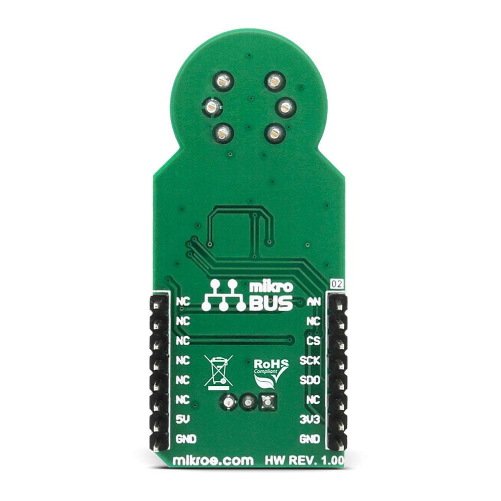
This table shows how the pinout of the Ozone 2 Click Board™ corresponds to the pinout on the mikroBUS™ socket (the latter shown in the two middle columns).
Notes | Pin | Pin | Notes | ||||
---|---|---|---|---|---|---|---|
Analog pin | AN | 1 | AN | PWM | 16 | NC | |
NC | 2 | RST | INT | 15 | NC | ||
SPI Chip Select | CS | 3 | CS | TX | 14 | NC | |
SPI clock | SCK | 4 | SCK | RX | 13 | NC | |
SPI Data OUT | SDO | 5 | MISO | SCL | 12 | NC | |
NC | 6 | MOSI | SDA | 11 | NC | ||
Power supply | +3.3V | 7 | 3.3V | 5V | 10 | +5V | Power supply |
Ground | GND | 8 | GND | GND | 9 | GND | Ground |
Onboard Jumpers and Settings
Label | Name | Default | Description |
---|---|---|---|
PWR | PWR | - | Power LED indicator |
JP1 | VCCIO SEL. | Left | Logic voltage level selection: left position 3V3, right position 5V |
JP2 | ADC SEL. | Left | Analog signal routing selection: left position - signal is routed to the ADC, right position - signal is routed to the AN pin of mikroBUS™ |
VR1 | - | - | Potentiometer for adjusting the sensor sensitivity |
Software Support
We provide a library for the Ozone 2 Click Board™ on our LibStock page, as well as a demo application (example), developed using MikroElektronika compilers. The demo can run on all the main MikroElektronika development boards.
Library Description
The library carries functions for initialization and reading the pa a digital value from MCP3351. Conversion of value to PPM is not covered by the library because it depends on the measurement environment.
Key functions
uint32_t ozone2_read()
- Reads a digital value from MCP3351 ADC circuit
Example Description
The application is composed of three sections :
- System Initialization - GPIO and SPI module initialization
- Application Initialization - SPI Driver initialization
- Application Task - reading raw digital value from ADC each one second and displaying it via UART terminal
void applicationTask() { readValue = ozone2_read(); LongWordToStr(readValue,text); mikrobus_logWrite("Read Value: ",_LOG_TEXT); mikrobus_logWrite(text,_LOG_LINE); Delay_ms(1000); }
Keep on mind that this is a raw measurement which should be converted to exact Ozone PPM value using formulas provided by circuit producer. Conversion to PPM depends on few conditions - more details
can be found in the datasheet.
The full application code, and ready to use projects can be found on our
LibStock page.
mikroE Libraries used in the example:
- UART
- SPI
- Conversions
Additional Notes and Information
Depending on the development board you are using, you may need a USB UART click, USB UART 2 click or RS232 click to connect to your PC, for development systems with no UART to USB interface available on the board. The terminal available in all MikroElektronika compilers, or any other terminal application of your choice, can be used to read the message.
mikroSDK
The Ozone 2 Click Board™ is supported with mikroSDK - MikroElektronika Software Development Kit. To ensure proper operation of mikroSDK compliant click board demo applications, mikroSDK should be downloaded from the LibStock and installed for the compiler you are using.
Ozone 2 Click Board
Frequently Asked Questions
Have a Question?
Be the first to ask a question about this.