SPI-Isolator-Click-Platine
Overview
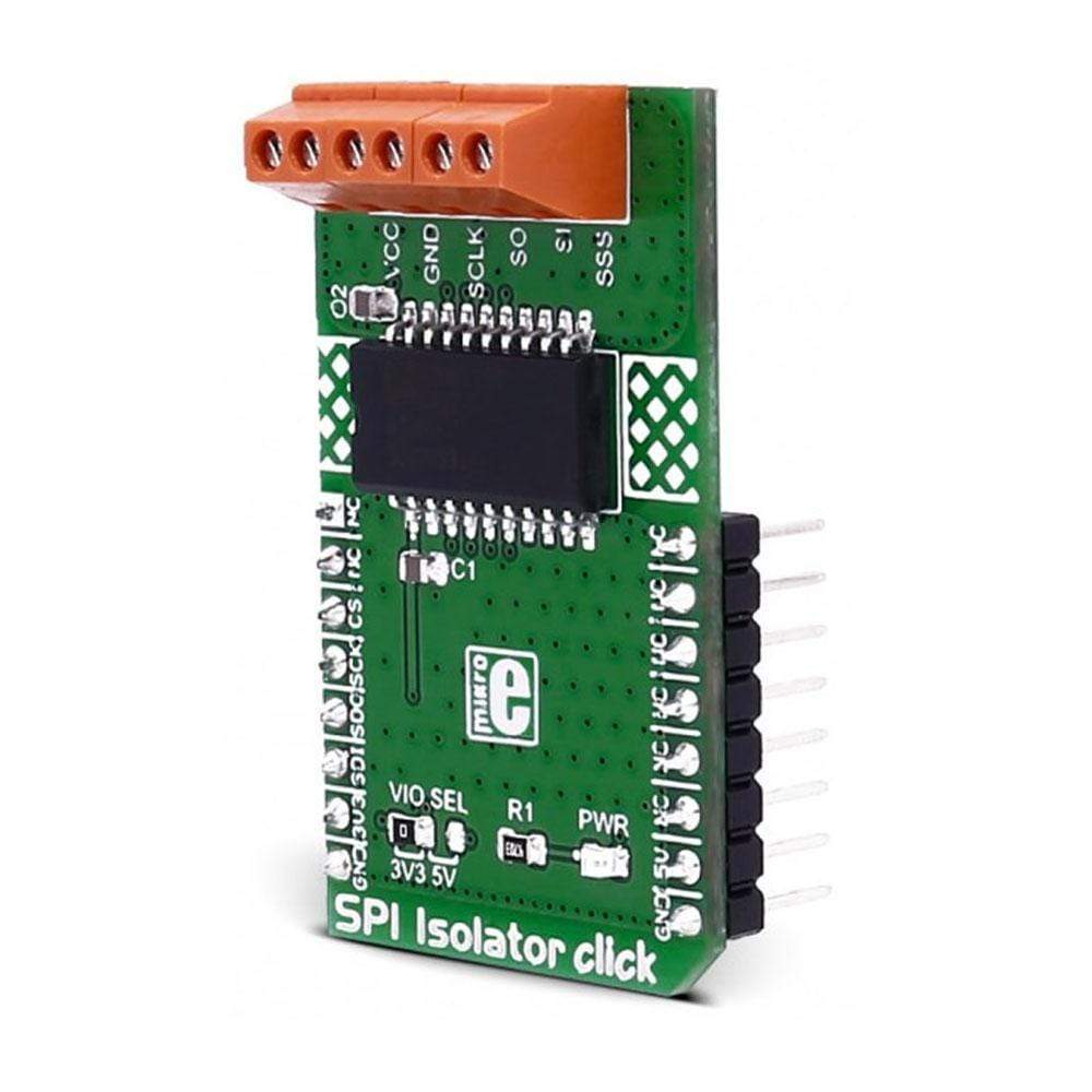
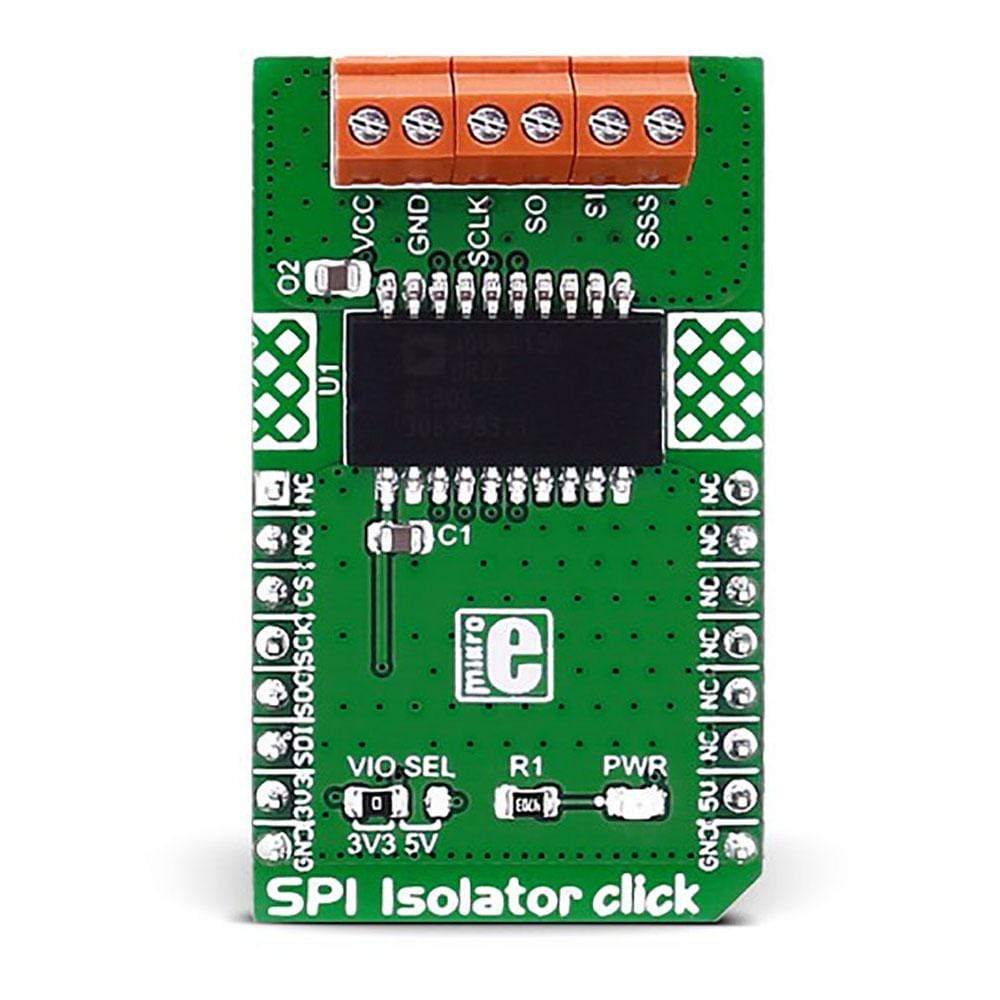
Das SPI Isolator Click Board™ verwendet den für eine serielle Peripherieschnittstelle (SPI) optimierten 5-kV-Digitalisolator ADuM4154 von Analog Devices.
Das SPI Isolator Click Board™ ist für den Betrieb mit 3,3 V oder 5 V Stromversorgung ausgelegt. Es kommuniziert mit dem Zielmikrocontroller über die SPI-Schnittstelle.
The SPI Isolator Click Board™ carries the ADuM4154 5kV digital isolator optimized for a serial peripheral interface (SPI), from Analog Devices. The click is designed to run on either 3.3V or 5V power supply. It communicates with the target microcontroller over SPI interface.
ADUM4154 FEATURES
The ADuM4154 has four high-speed channels. The first three channels, CLK, MI/SO, and MO/SI (the slash indicates the connection of the particular input and output channel across the isolator) are optimized for either low propagation delay in the B grade, or high noise immunity in the A grade.
Note: For more information about the A and B grade specifications see the datasheet.
Take a look at how the click can be connected in the picture below:
Note: For this example we used the ccRF 3 click and the EasyPIC v7 development board
SPI Communication
SPI (Serial Peripheral Interface) communication is one of the most popular protocols for sending data between microcontrollers and different peripherals.
It is a synchronous protocol; the clock signal is provided by the master.
For more information take a look at our Learn article about SPI communication.
SPECIFICATIONS
Type | SPI |
Applications | Sensor isolation, industrial programmable logic controllers (PLCs) |
On-board modules | ADuM4154 digital isolator optimized for SPI |
Key Features | The module supports up to 17 MHz SPI clock speed, 4 high speed, low propagation delay, SPI signal isolation channels |
Interface | SPI |
Compatibility | mikroBUS |
Click board size | M (42.9 x 25.4 mm) |
Input Voltage | 3.3V or 5V |
PINOUT DIAGRAM
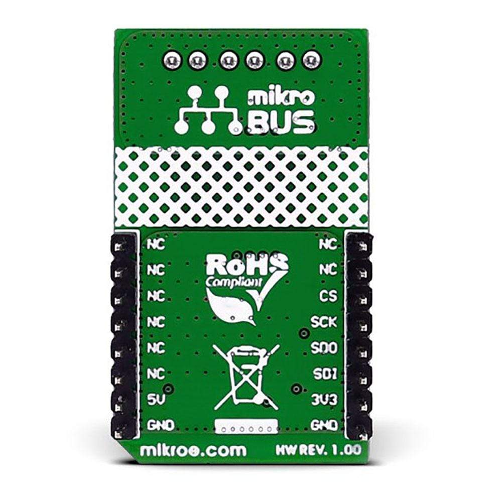
This table shows how the pinout of the SPI Isolator Click Board™ corresponds to the pinout on the mikroBUS™ socket (the latter shown in the two middle columns).
Notes | Pin | Pin | Notes | ||||
---|---|---|---|---|---|---|---|
NC | 1 | AN | PWM | 16 | NC | ||
NC | 2 | RST | INT | 15 | NC | ||
SPI Chip Select | CS | 3 | CS | TX | 14 | NC | |
SPI Clock | SCK | 4 | SCK | RX | 13 | NC | |
SPI Data OUT | SDO | 5 | MISO | SCL | 12 | NC | |
SPI Data IN | SDI | 6 | MOSI | SDA | 11 | NC | |
Power supply | +3.3V | 7 | 3.3V | 5V | 10 | +5V | Power supply |
Ground | GND | 8 | GND | GND | 9 | GND | Ground |
Frequently Asked Questions
Have a Question?
Be the first to ask a question about this.