


Mikroelektronika d.o.o.
LCD-Mono-Click-Platine
LCD-Mono-Click-Platine
SKU: MIKROE-3789
Verfügbarkeit für Abholungen konnte nicht geladen werden


Overview
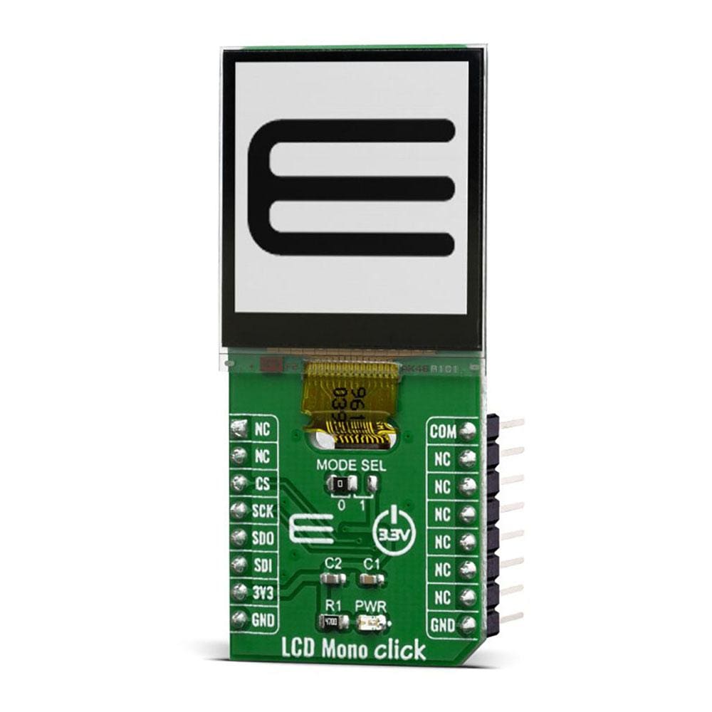
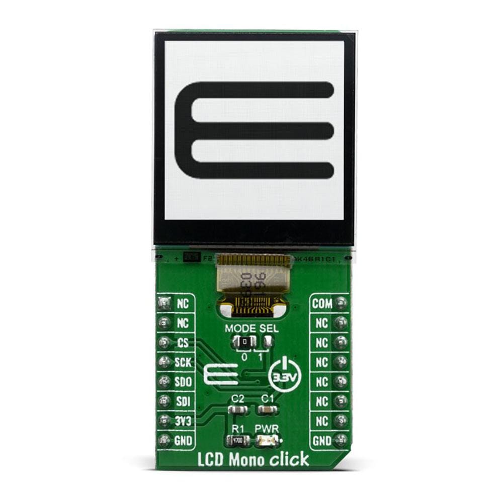
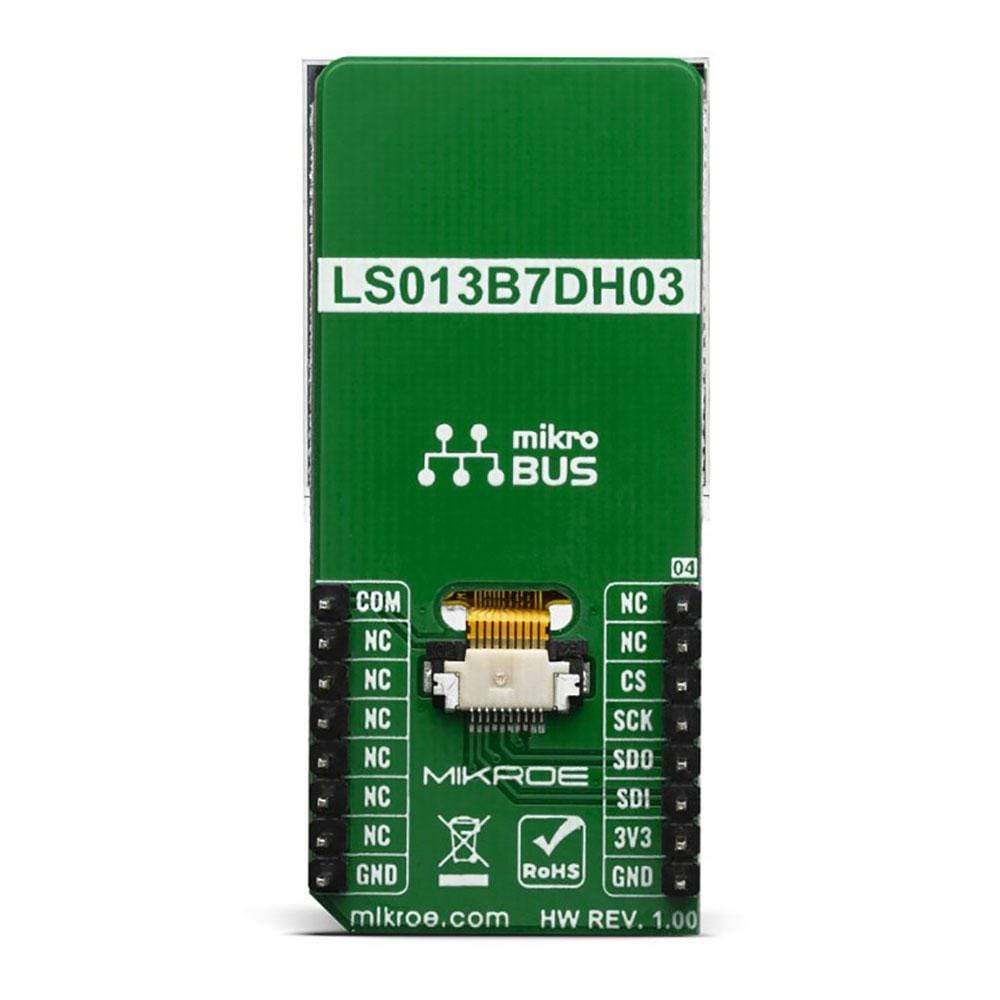
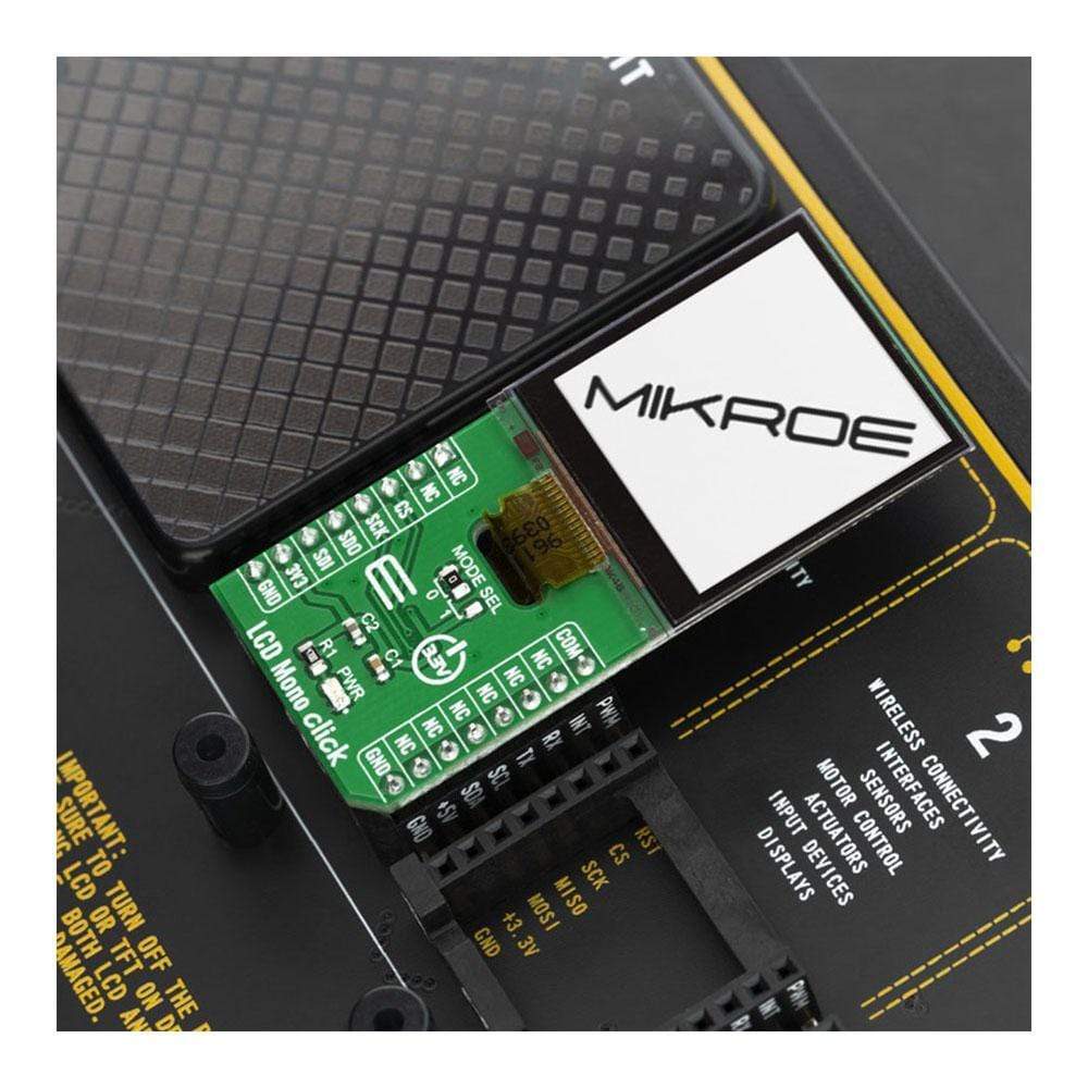
The LCD Mono Click Board™ uses the LS013B7DH03 LCD display from Sharp which combined with the EFM32, from Silicon Labs, and its energy-saving capabilities create a powerful display application. The application is capable of driving a 128x128 pixel display drawing as little as 2 µA while showing a static image. Even when updating the frame every second the current consumption can be lower than 5 µA.
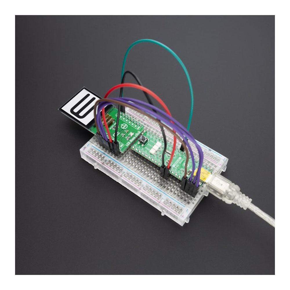
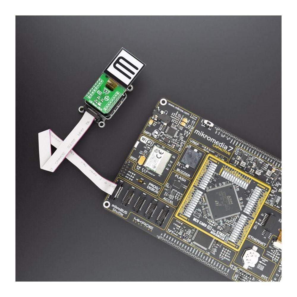
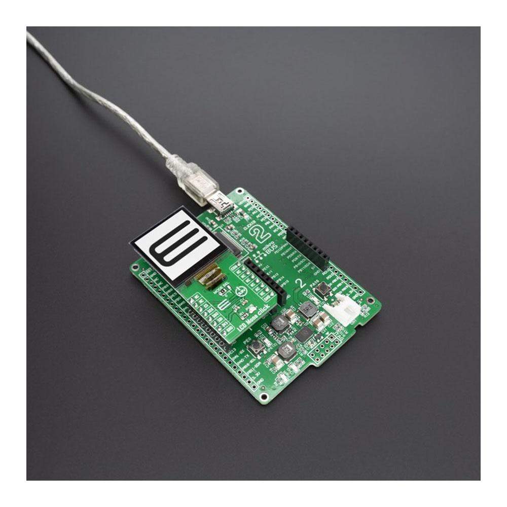
LCD Mono Click is supported by a mikroSDK compliant library, which includes functions that simplify software development. This Click Board™ comes as a fully tested product, ready to be used on a system equipped with the mikroBUS™ socket.
Downloads
Das LCD Mono Click Board™ verwendet das LCD-Display LS013B7DH03 von Sharp, das in Kombination mit dem EFM32 von Silicon Labs und seinen Energiesparfunktionen eine leistungsstarke Displayanwendung ergibt. Die Anwendung kann ein 128 x 128 Pixel großes Display mit nur 2 µA ansteuern und dabei ein statisches Bild anzeigen. Selbst wenn der Frame jede Sekunde aktualisiert wird, kann der Stromverbrauch unter 5 µA liegen.
LCD Mono Click wird von einer mikroSDK-kompatiblen Bibliothek unterstützt, die Funktionen enthält, die die Softwareentwicklung vereinfachen. Dieses Click Board™ wird als vollständig getestetes Produkt geliefert und ist bereit für den Einsatz auf einem System, das mit der mikroBUS™-Buchse ausgestattet ist.
| General Information | |
|---|---|
Part Number (SKU) |
MIKROE-3789
|
Manufacturer |
|
| Physical and Mechanical | |
Weight |
0.02 kg
|
| Other | |
EAN |
8606018719877
|
Frequently Asked Questions
Have a Question?
Be the first to ask a question about this.