IR Sense Click-Platine
Overview
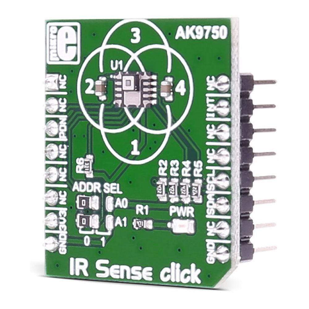
Das IR Sense Click Board™ verwendet den Quanten-IR-Sensor AK9750. Das Click Board™ ist für den Betrieb mit einer 3,3-V-Stromversorgung ausgelegt.
Es kommuniziert mit dem Zielmikrocontroller über die I2C-Schnittstelle, wobei zusätzliche Funktionen durch den INT-Pin auf der MikroBUS-Leitung bereitgestellt werden.
The IR Sense Click Board™ carries the AK9750 quantum-type IR sensor. The click is designed to run on a 3.3V power supply. It communicates with the target microcontroller over I2C interface, with additional functionality provided by the INT pin on the mikroBUS™ line.
The IR Sense Click Board™ detects the temperature of objects and people in motion. It can also detect a human body that remains still. So, it distinguishes heat regardless of the fact whether or not an object is moving.
AK9750 FEATURES
The AK9750 is an ultra-low power and compact infrared-ray (IR) sensor module. It is composed of four quantum IR sensors and an integrated circuit (IC) for characteristic compensation.
An integral analog-to-digital converter provides 16-bits data outputs. Additional integrated features include a field of view limiter and an optical filter.
How Does The IR Sense Click Board™ Work?
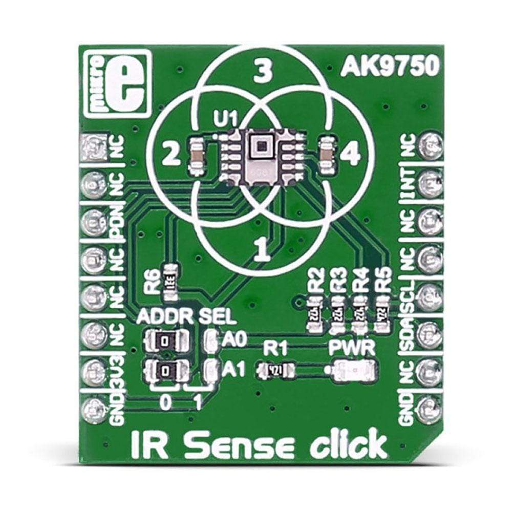
The IR sensors are arranged as shown. Each sensor detects the diagonal area, as indicated in the image below:
The observable area of the four sensors is as you see it on the silk of the IR Sense Click Board™.
SPECIFICATIONS
Type | Temperature & humidity |
Applications | Detecting heat with the four IR sensors |
On-board modules | AK9750 IR sensor |
Key Features | Low current consumption: Max. 1µA in Power down Mode; Integrated temperature sensor, 16-bits Digital Outputs to I2C bus |
Interface | I2C |
Compatibility | mikroBUS |
Click board size | S (28.6 x 25.4 mm) |
Input Voltage | 3.3V |
PINOUT DIAGRAM
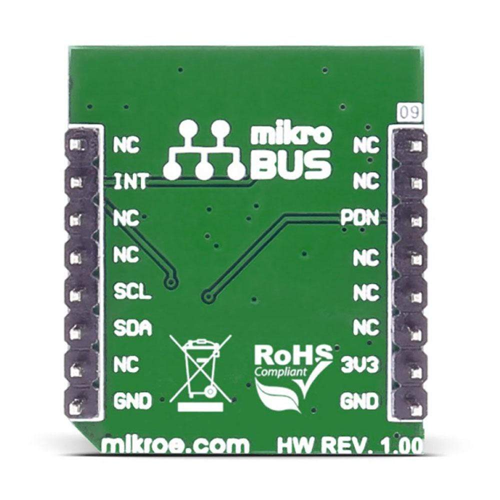
This table shows how the pinout on the IR Sense Click Board™ corresponds to the pinout on the mikroBUS™ socket (the latter shown in the two middle columns).
Notes | Pin | Pin | Notes | ||||
---|---|---|---|---|---|---|---|
ALR | 1 | AN | PWM | 16 | NC | ||
NC | 2 | RST | INT | 15 | INT | Interrupt | |
Power down pin | PDN | 3 | CS | TX | 14 | NC | |
NC | 4 | SCK | RX | 13 | NC | ||
NC | 5 | MISO | SCL | 12 | SCL | SCL I2C line | |
NC | 6 | MOSI | SDA | 11 | SDA | SDA I2C line | |
Power supply | +3.3V | 7 | 3.3V | 5V | 10 | NC | |
Ground | GND | 8 | GND | GND | 9 | GND | Ground |
JUMPERS AND SETTINGS
Designator | Name | Default Position | Default Option | Description |
---|---|---|---|---|
A0 | A0 | Left | 0 | Selection of I2C address bit 0 |
A1 | A1 | Left | 1 | Selection of I2C address bit 1 |
Software Support
Code examples for the IR Sense Click Board™, written for MikroElektronika hardware and compilers are available on Libstock.
CODE SNIPPET
The following code snippet shows the main loop of the IR Sense click example, which reads data every few second and then displays it via UART.
01 while( 1 ) 02 { 03 Delay_ms (5000); 04 05 06 IRGRID2_readAll (readData); 07 08 //Upper area sensor value 09 UART2_Write_Text ("rn "); 10 tempValue = readData [5] + ( readData [6] << 8 ); 11 IntToStr (tempValue, uartText); 12 UART2_Write_Text (uartText); 13 14 //Left area sensor value 15 UART2_Write_Text ("rn"); 16 tempValue = readData [3] + ( readData [4] << 8 ); 17 IntToStr (tempValue, uartText); 18 UART2_Write_Text (uartText); 19 //Right area sensor value 20 UART2_Write_Text (" "); 21 tempValue = readData [7] + ( readData [8] << 8 ); 22 IntToStr (tempValue, uartText); 23 UART2_Write_Text (uartText); 24 25 //Lower area sensor value 26 UART2_Write_Text ("rn "); 27 tempValue = readData [1] + ( readData [2] << 8 ); 28 IntToStr (tempValue, uartText); 29 UART2_Write_Text (uartText); 30 UART2_Write_Text ("rn-------------"); 31 }
Frequently Asked Questions
Have a Question?
Be the first to ask a question about this.