Mikroelektronika d.o.o.
iButton Click-Platine
Verfügbarkeit für Abholungen konnte nicht geladen werden


Overview
Das iButton Click Board™ ist eine iButton-Sonde. Die iButton-Technologie basiert auf dem Eindraht-Kommunikationsprotokoll und einem Chip, der normalerweise in einem robusten Edelstahlgehäuse verpackt ist. Das knopfförmige iButton-Gerät hat zwei Kontakte – den Deckel und die Basis. Diese Kontakte führen die notwendigen Verbindungen zu einem empfindlichen Siliziumchip, der in den Metallknopf eingebettet ist. Wenn der iButton die Lesesonde auf dem iButton Click Board™ berührt, stellt er über die Eindrahtschnittstelle die Kommunikation mit der Host-MCU her. Die Kommunikation erfolgt nahezu augenblicklich, es reicht also aus, den iButton leicht auf die Sondenkontakte zu drücken.
General Information | |
---|---|
Part Number (SKU) |
MIKROE-3045
|
Manufacturer |
|
Physical and Mechanical | |
Weight |
0.026 kg
|
Other | |
Country of Origin |
|
HS Code Customs Tariff code
|
|
EAN |
8606018713097
|
Warranty |
|
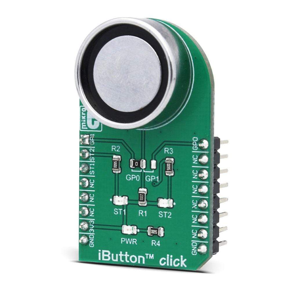
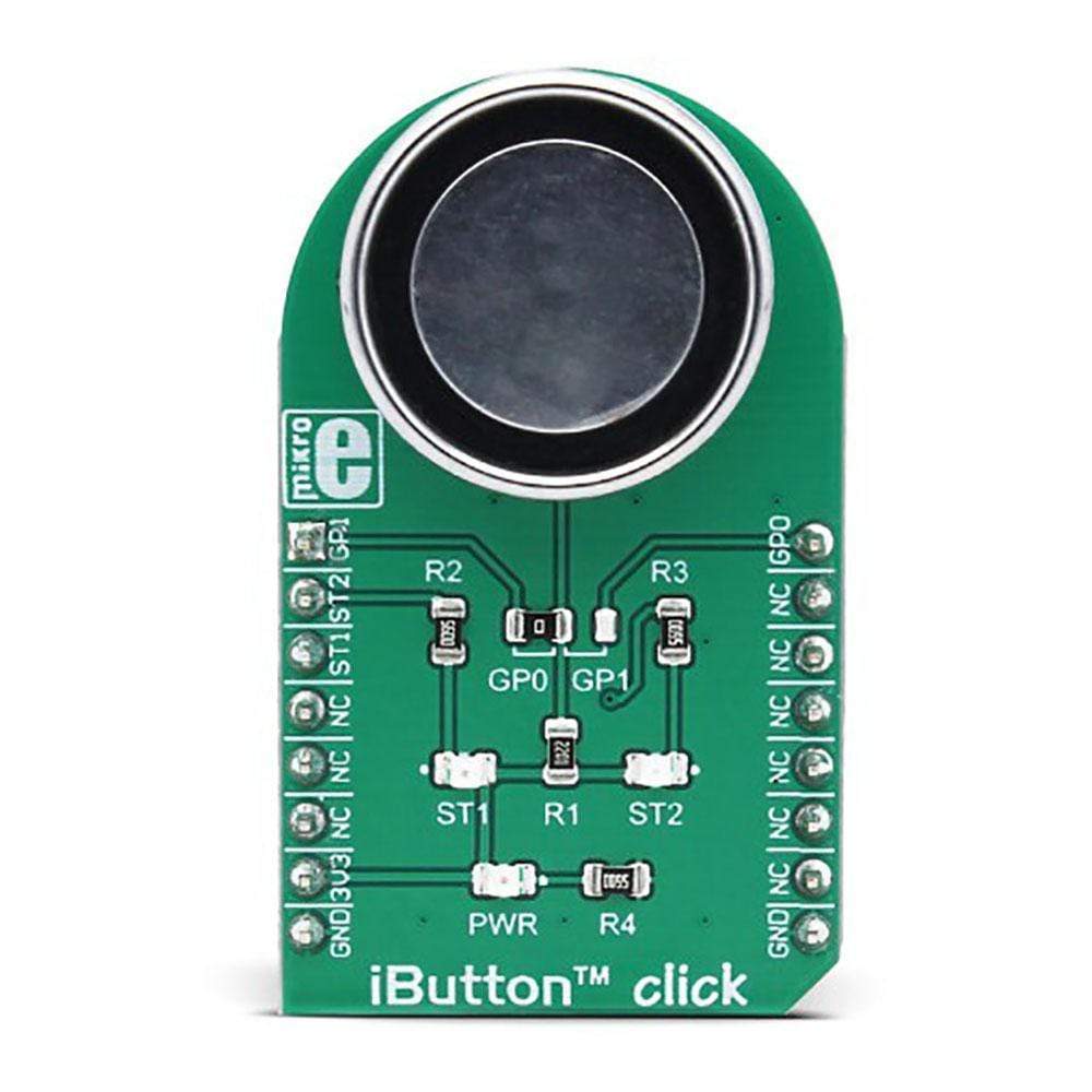
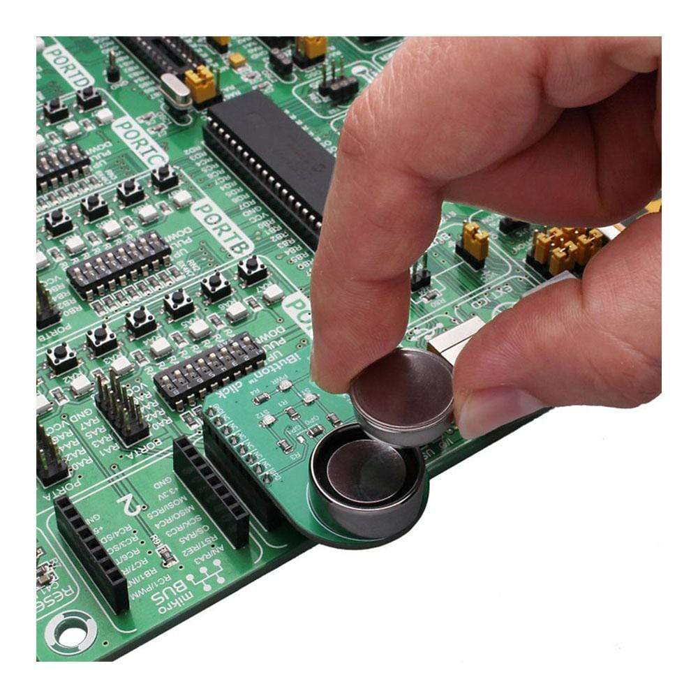
The iButton Click Board™ - is an iButton™ probe. The iButton is a technology based on the 1-Wire® communication protocol, and a chip usually packed in a robust stainless steel casing. The button-shaped iButton device has two contacts - the lid and the base. These contacts carry the necessary connections down to a sensitive silicone chip, embedded inside the metal button. When the iButton touches the reader probe on the Click board™, it establishes the communication with the host MCU, via the 1-Wire® interface. The communication is almost instant, so it is enough to press the iButton lightly to the probe contacts.
Due to its robustness, the iButton can withstand much more stress than similar devices used to carry an information: tags, cards, and other such devices are prone to damage, while a chip packed inside a thick stainless steel can be highly resilient. This Click board™ carries an iButton probe, along with two LEDs. It can be used to interface any iButton with the host MCU, displaying the resulting status information on any of the two independently programmed LEDs. This Click board™ is very useful for building a wide range of applications that can utilize a wide number of different iButton devices.
How Does The iButton Click Board™ Work?
The iButton Click Board™ carries the CZ-0-PIN, a high-quality iButton probe from Demiurge company. The metal probe ensures resistance to dirt, dust, moisture, shock and other environmental hazards while ensuring good alignment with the iButton device, at the same time. The manufacturer guarantees compatibility with Maxim iButton devices, but any other device compatible with the maxim iButton can be read by the probe.
The iButton device is capable of powering itself up through the data line by employing the so-called parasite power supply. The iButton Click Board™ is equipped with the pull-up resistor to the 3.3V mikroBUS™ rail, providing power for the iButton that way. So-called parasite PSU of the iButton contains an internal capacitor, which provides enough current for the proper operation, once it has been charged by the data line. To allow proper functioning of the parasitic PSU, the idle state of the data line is HIGH, while the data line of the iButton device is in an open-drain configuration, pulling the data line to a LOW logic level when asserted.
The 1-Wire communication line is routed to the SMD jumper, which allows routing of the 1-Wire communication either to the PWM pin or to the AN pin of the mikroBUS™. These pins are labeled GP0 and GP1 respectively, the same as the SMD jumper positions, making the selection of the desired pin simple and straightforward.
The green LED labeled as ST1 is routed to the RST pin of the mikroBUS™, while the red LED is labelled as ST2 and it is routed to the CS pin of the mikroBUS™. These two pins allow visual feedback from the software, for example, if the serial number of the docked iButton matches the authorization criteria, the green LED can be used to signal it. These LEDs are can be used for any type of signalization, and are not directly connected with the iButton device itself.
SPECIFICATIONS
Type | 1-Wire |
Applications | An ideal solution for building a wide range of applications that can utilize a wide number of different iButton devices |
On-board modules | CZ-0-PIN, a high quality iButton probe from Demiurg company |
Key Features | The metal probe ensures good alignment of the iButton device, two programmable LEDs that can be used for the status report, simple software development with the included library functions |
Interface | 1-Wire |
Compatibility | mikroBUS |
Click board size | M (42.9 x 25.4 mm) |
Input Voltage | 3.3V |
PINOUT DIAGRAM
This table shows how the pinout of the iButton Click Board™ corresponds to the pinout on the mikroBUS™ socket (the latter shown in the two middle columns).
Notes | Pin | ![]() |
Pin | Notes | |||
---|---|---|---|---|---|---|---|
1-Wire Data IN/OUT | GP0 | 1 | AN | PWM | 16 | GP1 | 1-Wire Data IN/OUT |
Red LED Cathode | ST2 | 2 | RST | INT | 15 | NC | |
Green LED Cathode | ST1 | 3 | CS | RX | 14 | NC | |
NC | 4 | SCK | TX | 13 | NC | ||
NC | 5 | MISO | SCL | 12 | NC | ||
NC | 6 | MOSI | SDA | 11 | NC | ||
Power supply | +3.3V | 7 | 3.3V | 5V | 10 | NC | |
Ground | GND | 8 | GND | GND | 9 | GND | Ground |
ONBOARD SETTINGS AND INDICATORS
Label | Name | Default | Description |
---|---|---|---|
PWR | PWR | - | Power LED indicator |
ST1 | ST1 | - | User programmable GREEN LED |
ST2 | ST2 | - | User programmable RED LED |
JP1 | GP0, GP1 | Left | 1-Wire data comm. pin selection: left position GP0, right position GP1 |
Frequently Asked Questions
Have a Question?
Be the first to ask a question about this.