


Hantek Electronic Co Ltd
Hantek HDM3065 6½-stelliges TrueRMS-Digitalmultimeter
Hantek HDM3065 6½-stelliges TrueRMS-Digitalmultimeter
SKU: HDM3065
Verfügbarkeit für Abholungen konnte nicht geladen werden


Overview
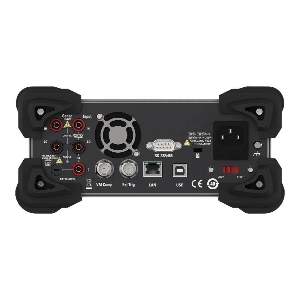
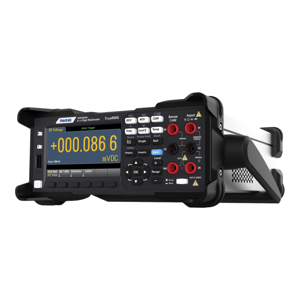
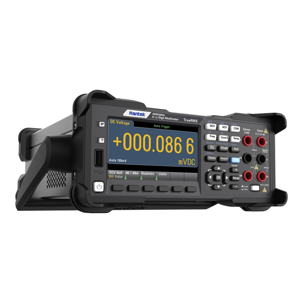
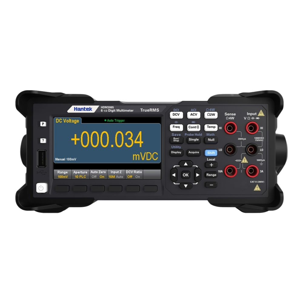
The Hantek HDM3065 series 6½ digit bench multimeter is a brand-new addition to the Hantek family. Based on modern styling, it would be a proud addition to the bench of any electronic engineer. It offers excellent value.
The enhanced resolution and its superb reading rate make this multimeter ideal for capturing transient signals with accuracy.
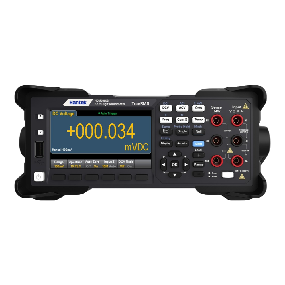
The multimeter is based on a 4.3", 64K colour LCD display with a dual-display of measured signals in two different formats.
The HDM3065 can also be controlled from a host PC with the supplied PC software.
Downloads
Das 6½-stellige Tischmultimeter der Hantek HDM3065-Serie ist eine brandneue Ergänzung der Hantek-Familie. Mit seinem modernen Design wäre es eine stolze Ergänzung für den Schreibtisch eines jeden Elektronikingenieurs. Es bietet ein hervorragendes Preis-Leistungs-Verhältnis.
Dank der verbesserten Auflösung und der hervorragenden Lesegeschwindigkeit eignet sich dieses Multimeter ideal für die genaue Erfassung transienter Signale.
Das Multimeter basiert auf einem 4,3" 64K-Farb-LCD-Display mit einer Dual-Anzeige der gemessenen Signale in zwei unterschiedlichen Formaten.
Der HDM3065 kann mit der mitgelieferten PC-Software auch von einem Host-PC aus gesteuert werden.
| General Information | |
|---|---|
Part Number (SKU) |
HDM3065
|
| Physical and Mechanical | |
Weight |
3.8 kg
|
| Other | |
EAN |
5055383620333
|
Frequently Asked Questions
Have a Question?
-
Does it come with a calibration certificate?
Yes, the HDM3065 comes with a basic calibration certificate.