


Mikroelektronika d.o.o.
Fan 4 Click-Platine
Fan 4 Click-Platine
SKU: MIKROE-3200
Verfügbarkeit für Abholungen konnte nicht geladen werden

Overview
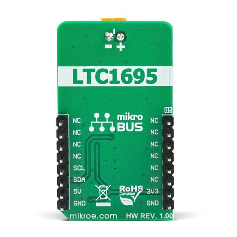
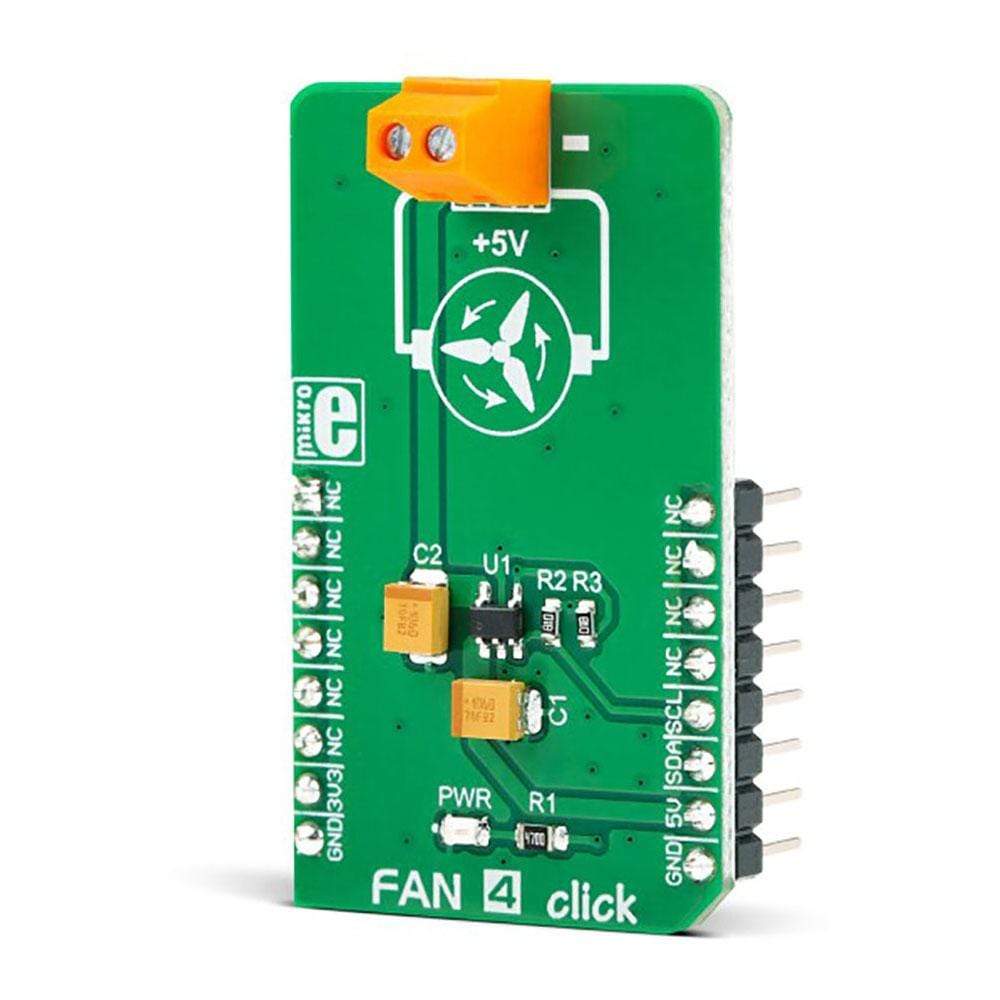
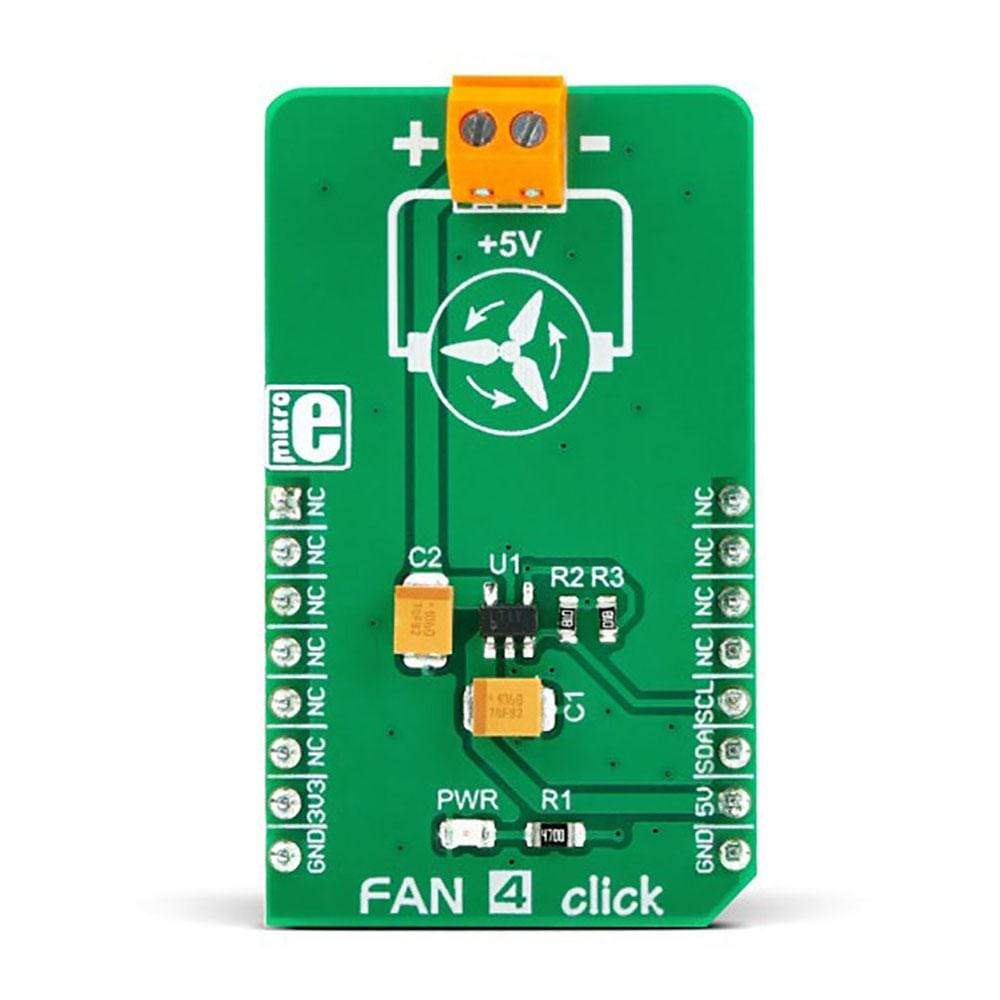
The Fan 4 Click Board™ is a very compact, two-wire fan driver. It utilizes an integrated 5V, DC, brushless-motor driver chip. Its output voltage regulation and current limiting capabilities allow the speed control for the two-wire DC brushless motors. The Click Board™ uses the LTC1695 IC, which features an integrated 6-bit DAC. The DAC regulates the output voltage in the range from 0 to 4.92V. This IC also has some additional features, such as the maximum output current limiting, and thermal shutdown protection. There is also a startup boost timer which ensures reliable startup of the fan, connected to the output terminal.
Downloads
Das Fan 4 Click Board™ ist ein sehr kompakter, zweiadriger Lüftertreiber. Es verwendet einen integrierten bürstenlosen 5-V-DC-Motortreiberchip. Seine Ausgangsspannungsregelung und Strombegrenzungsfunktionen ermöglichen die Drehzahlregelung für die zweiadrigen bürstenlosen DC-Motoren. Das Click Board™ verwendet den LTC1695 IC, der über einen integrierten 6-Bit-DAC verfügt. Der DAC regelt die Ausgangsspannung im Bereich von 0 bis 4,92 V. Dieser IC verfügt außerdem über einige zusätzliche Funktionen, wie z. B. die Begrenzung des maximalen Ausgangsstroms und einen thermischen Abschaltschutz. Es gibt auch einen Start-Boost-Timer, der einen zuverlässigen Start des Lüfters gewährleistet, der an die Ausgangsklemme angeschlossen ist.
| General Information | |
|---|---|
Part Number (SKU) |
MIKROE-3200
|
Manufacturer |
|
| Physical and Mechanical | |
Weight |
0.019 kg
|
| Other | |
EAN |
8606018713660
|
Frequently Asked Questions
Have a Question?
Be the first to ask a question about this.