


Mikroelektronika d.o.o.
CAN FD Click-Platine
CAN FD Click-Platine
SKU: MIKROE-3933
Verfügbarkeit für Abholungen konnte nicht geladen werden


Overview
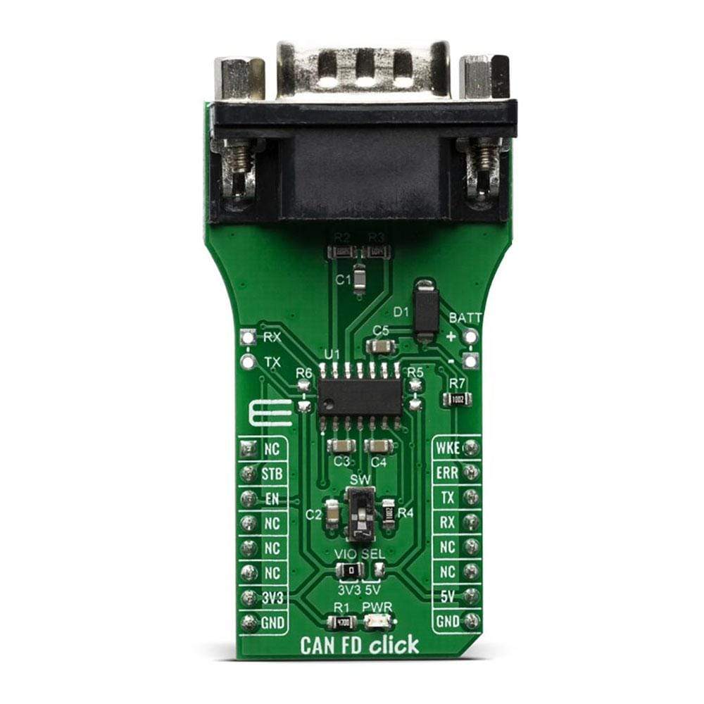
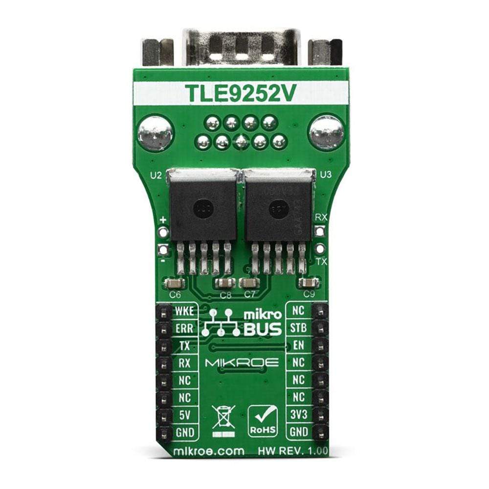
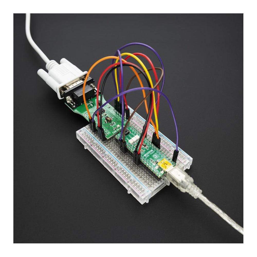
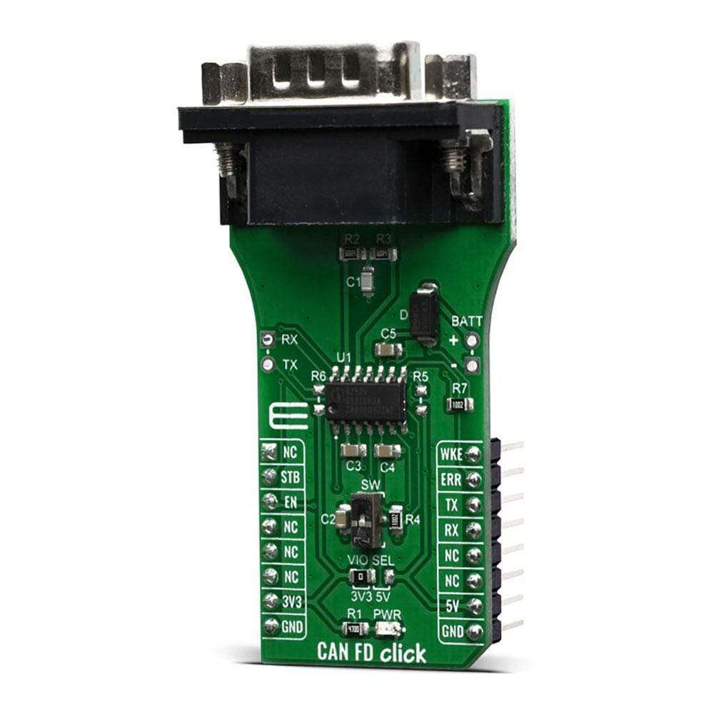
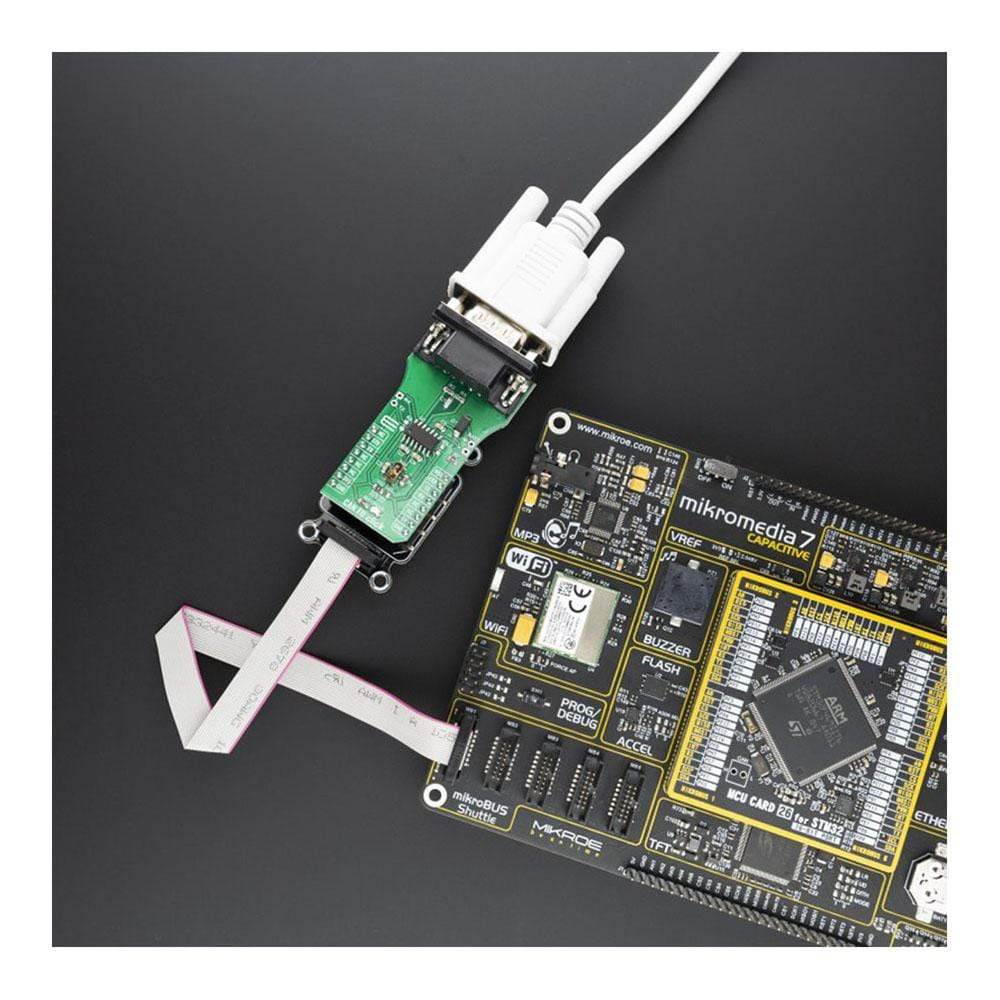
The CAN FD Click Board™ is an add-on board based on TLE9252V CAN network transceiver, designed for HS CAN network up to 5 Mbit/s in automotive and industrial applications. As an interface between the physical bus layer and the CAN protocol controller, the TLE9252V drives the signals to the bus and protects the microcontroller against interference generated within the network.
Given all the features its components offer, the CAN FD Click Board™ is best used for for infotainment applications, cluster modules, radar applications and HVAC.
Downloads
Das CAN FD Click Board™ ist eine Zusatzplatine basierend auf dem TLE9252V CAN-Netzwerk-Transceiver, entwickelt für HS CAN-Netzwerke mit bis zu 5 Mbit/s in Automobil- und Industrieanwendungen. Als Schnittstelle zwischen der physischen Busschicht und dem CAN-Protokollcontroller überträgt das TLE9252V die Signale an den Bus und schützt den Mikrocontroller vor Störungen, die im Netzwerk entstehen.
Aufgrund aller Funktionen, die seine Komponenten bieten, eignet sich das CAN FD Click Board™ am besten für Infotainment-Anwendungen, Cluster-Module, Radaranwendungen und HVAC.
| General Information | |
|---|---|
Part Number (SKU) |
MIKROE-3933
|
Manufacturer |
|
| Physical and Mechanical | |
Weight |
0.03 kg
|
| Other | |
EAN |
8606018718931
|
Frequently Asked Questions
Have a Question?
Be the first to ask a question about this.