


Mikroelektronika d.o.o.
Bürstenloses 7-Click-Board
Bürstenloses 7-Click-Board
SKU: MIKROE-4182
Verfügbarkeit für Abholungen konnte nicht geladen werden
Overview
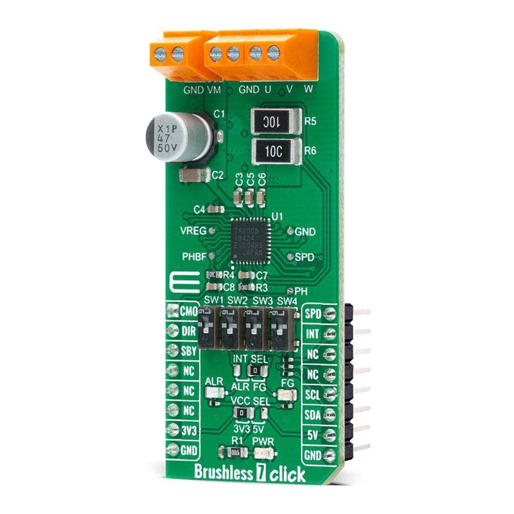
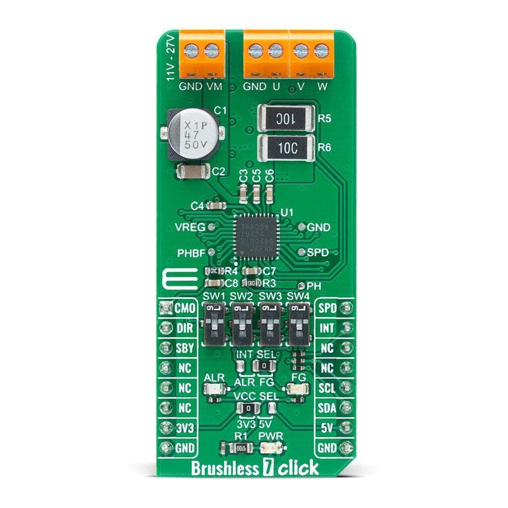
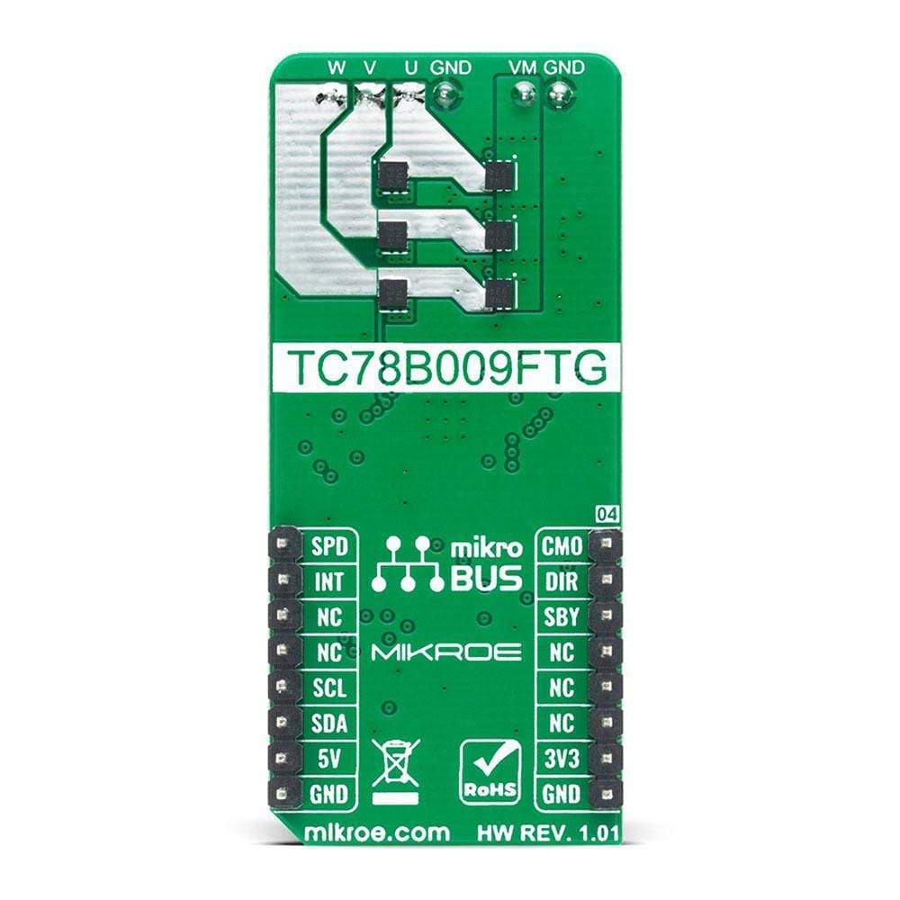
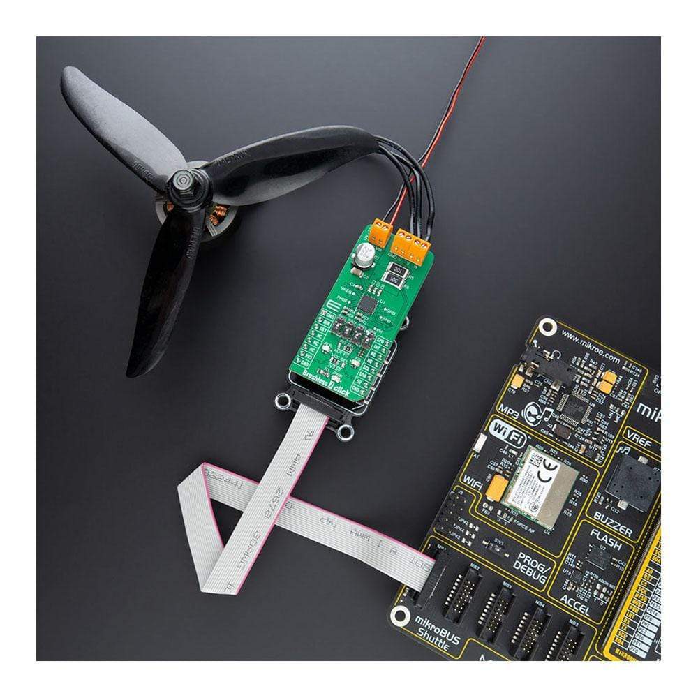
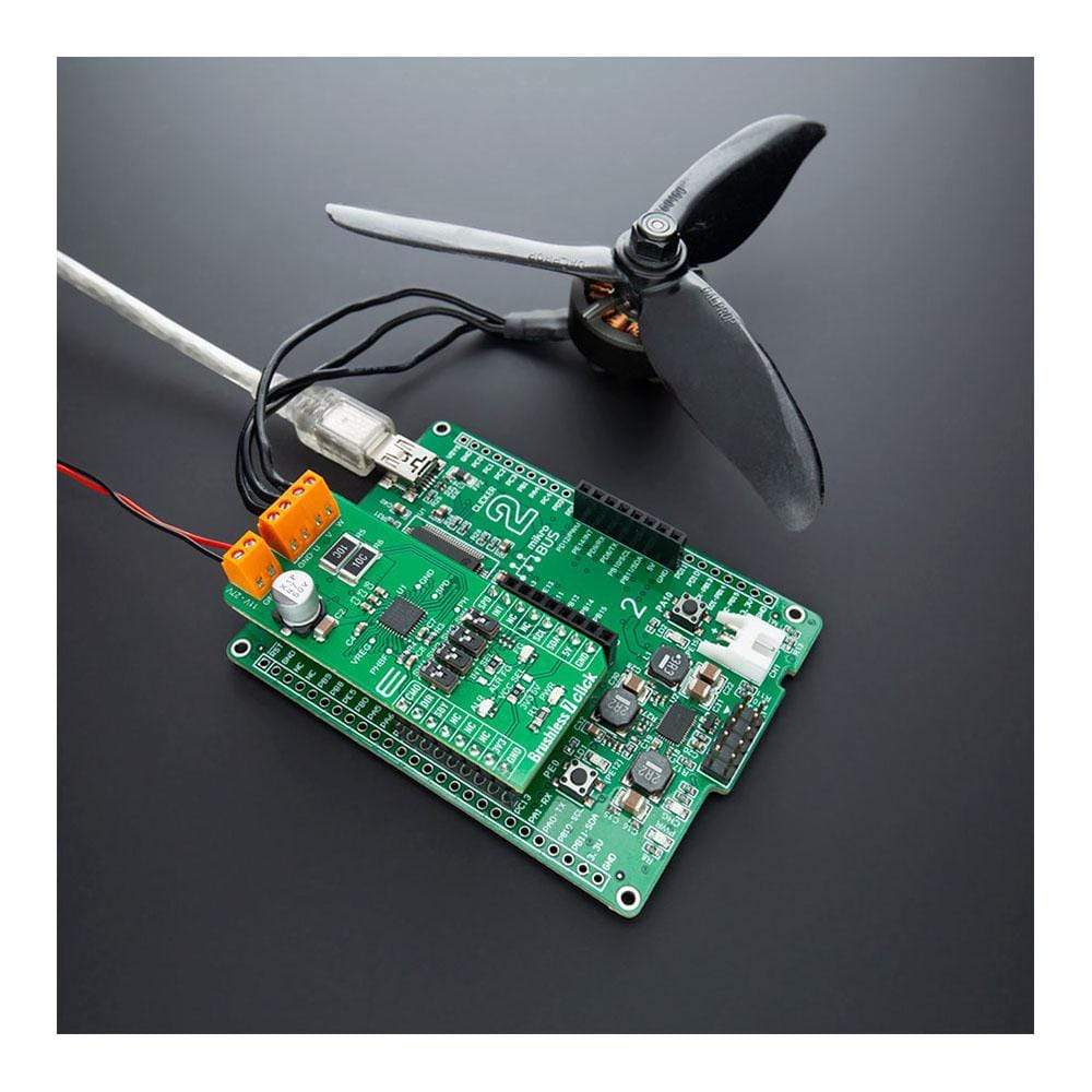
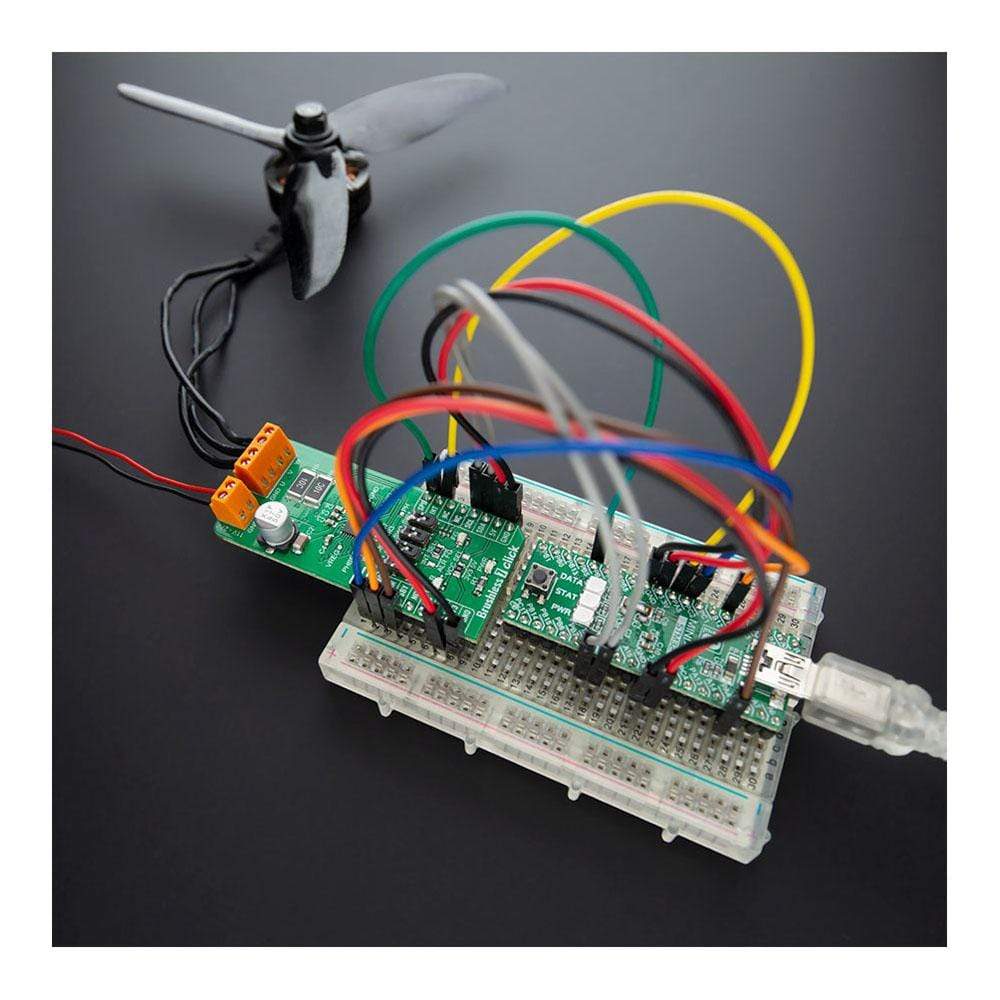
The Brushless 7 Click Board™ is, as its name said, a motor driver based expansion board for controlling BLCD motors with any microcontroller. The board is based on TC78B009FTG IC from Toshiba, which is a three-phase BLDC motor controller that does not require Hall sensors.
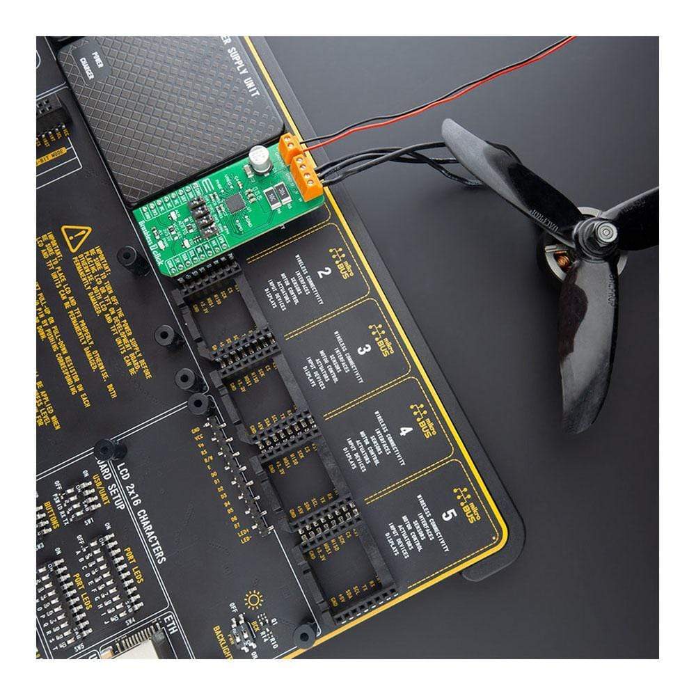
Some of the main features are a built-in closed-loop speed control function that regulates and maintains the motor rotational speed under dynamic power fluctuations and load variations. With the precise setting of a speed profile done by the built-in nonvolatile memory (NVM), it eliminates the need for an external MCU for closed-loop speed control and makes it the perfect solution for applications that include high-speed fans used in servers, blowers, cordless vacuum cleaners, and robot vacuum cleaners.
Downloads
Das Brushless 7 Click Board™ ist, wie der Name schon sagt, eine auf Motortreibern basierende Erweiterungskarte zur Steuerung von BLDC-Motoren mit jedem Mikrocontroller. Die Karte basiert auf dem IC TC78B009FTG von Toshiba, einem dreiphasigen BLDC-Motorcontroller, der keine Hallsensoren benötigt.
Zu den Hauptfunktionen gehört eine integrierte Drehzahlregelungsfunktion, die die Motordrehzahl bei dynamischen Leistungsschwankungen und Lastschwankungen regelt und aufrechterhält. Durch die präzise Einstellung eines Drehzahlprofils durch den integrierten nichtflüchtigen Speicher (NVM) wird keine externe MCU für die Drehzahlregelung benötigt. Dies macht es zur perfekten Lösung für Anwendungen wie Hochgeschwindigkeitslüfter, die in Servern, Gebläsen, kabellosen Staubsaugern und Roboterstaubsaugern verwendet werden.
| General Information | |
|---|---|
Part Number (SKU) |
MIKROE-4182
|
Manufacturer |
|
| Physical and Mechanical | |
Weight |
0.022 kg
|
| Other | |
EAN |
8606027380020
|
Frequently Asked Questions
Have a Question?
Be the first to ask a question about this.