


Mikroelektronika d.o.o.
Analoge Key Click-Platine
Analoge Key Click-Platine
SKU: MIKROE-3409
Verfügbarkeit für Abholungen konnte nicht geladen werden

Overview
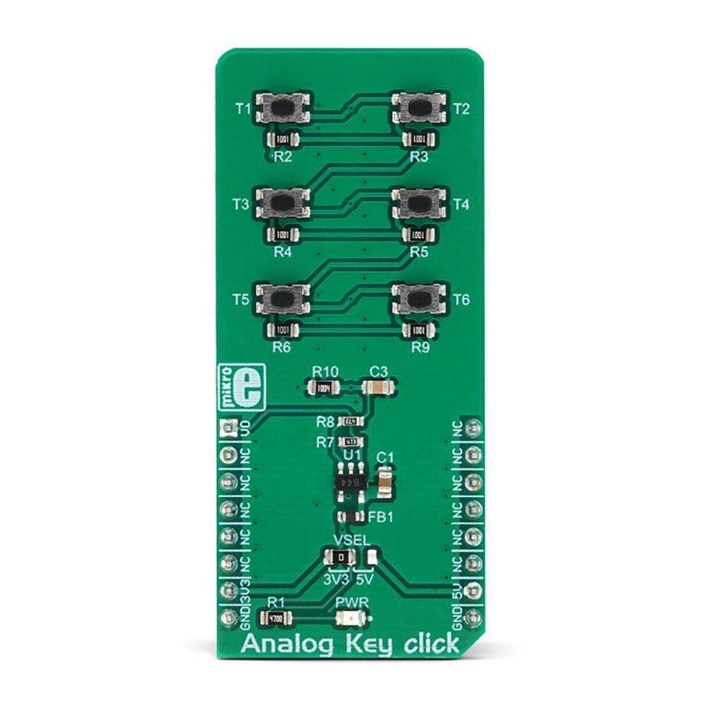
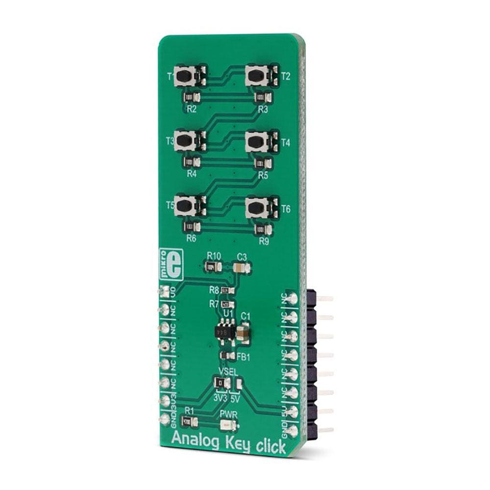
The Analog Key Click Board™ is an analogue keyboard on a Click Board™. It contains six tactile pushbuttons, used to select one of six different voltage levels. The idea behind this Click Board™ is very simple: six resistors form a voltage divider. The resistors are connected in series between the VCC and the GND. Each button selects one of the six middle taps, allowing six different voltage levels to be selected. The voltage is available at the AN pin of the mikroBUS, which is additionally protected by an operational amplifier, configured as a buffer. This allows both protection and a proper impedance at the analogue input pin of the microcontroller.
Downloads
Das Analog Key Click Board™ ist eine analoge Tastatur auf einem Click Board™. Es enthält sechs taktile Drucktasten, mit denen einer von sechs verschiedenen Spannungspegeln ausgewählt werden kann. Die Idee hinter diesem Click Board™ ist sehr einfach: Sechs Widerstände bilden einen Spannungsteiler. Die Widerstände sind in Reihe zwischen VCC und GND geschaltet. Jede Taste wählt einen der sechs mittleren Abgriffe aus, sodass sechs verschiedene Spannungspegel ausgewählt werden können. Die Spannung ist am AN-Pin des MikroBUS verfügbar, der zusätzlich durch einen als Puffer konfigurierten Operationsverstärker geschützt ist. Dies ermöglicht sowohl Schutz als auch eine angemessene Impedanz am analogen Eingangspin des Mikrocontrollers.
| General Information | |
|---|---|
Part Number (SKU) |
MIKROE-3409
|
Manufacturer |
|
| Physical and Mechanical | |
Weight |
0.023 kg
|
| Other | |
EAN |
8606018714742
|
Frequently Asked Questions
Have a Question?
Be the first to ask a question about this.