Tableau de clic Watchdog
Overview
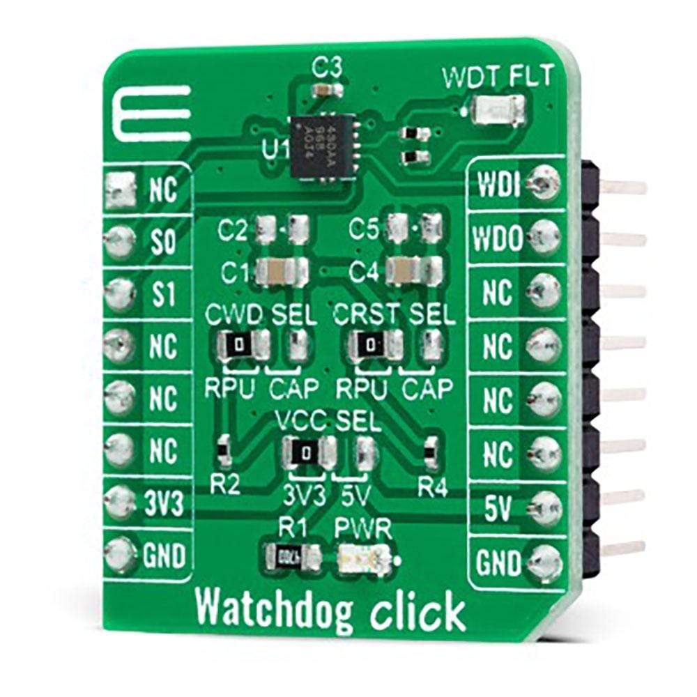
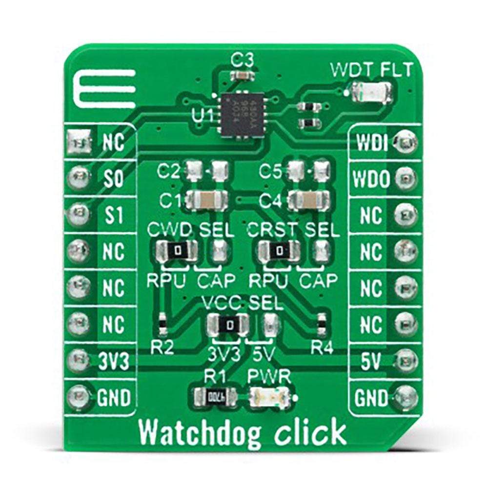
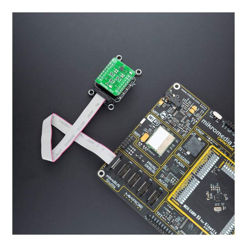
Le Watchdog Click Board™ est une carte complémentaire compacte qui contient un compte à rebours simple pour une grande variété d'applications. Cette carte comprend le TPS3430, un minuteur de surveillance autonome avec une fenêtre de surveillance programmable et un délai de réinitialisation programmable de Texas Instruments. Le TPS3430 a le délai de réinitialisation de la sortie du chien de garde défini par les paramètres de délai par défaut programmés en usine ou programmés par un condensateur externe. Il atteint une précision de synchronisation de 2,5 % à la température typique de 25 °C et peut être désactivé via deux broches SET pour éviter les dépassements de délai de surveillance indésirables pendant le processus de développement ou la mise sous tension. Ce Click Board™ peut être utilisé comme compte à rebours dans les MCU, DSP, FPGA, ASIC et bien d'autres.
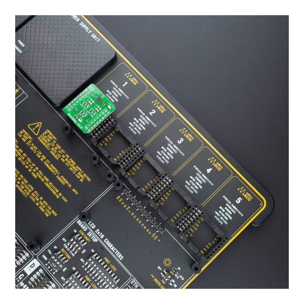
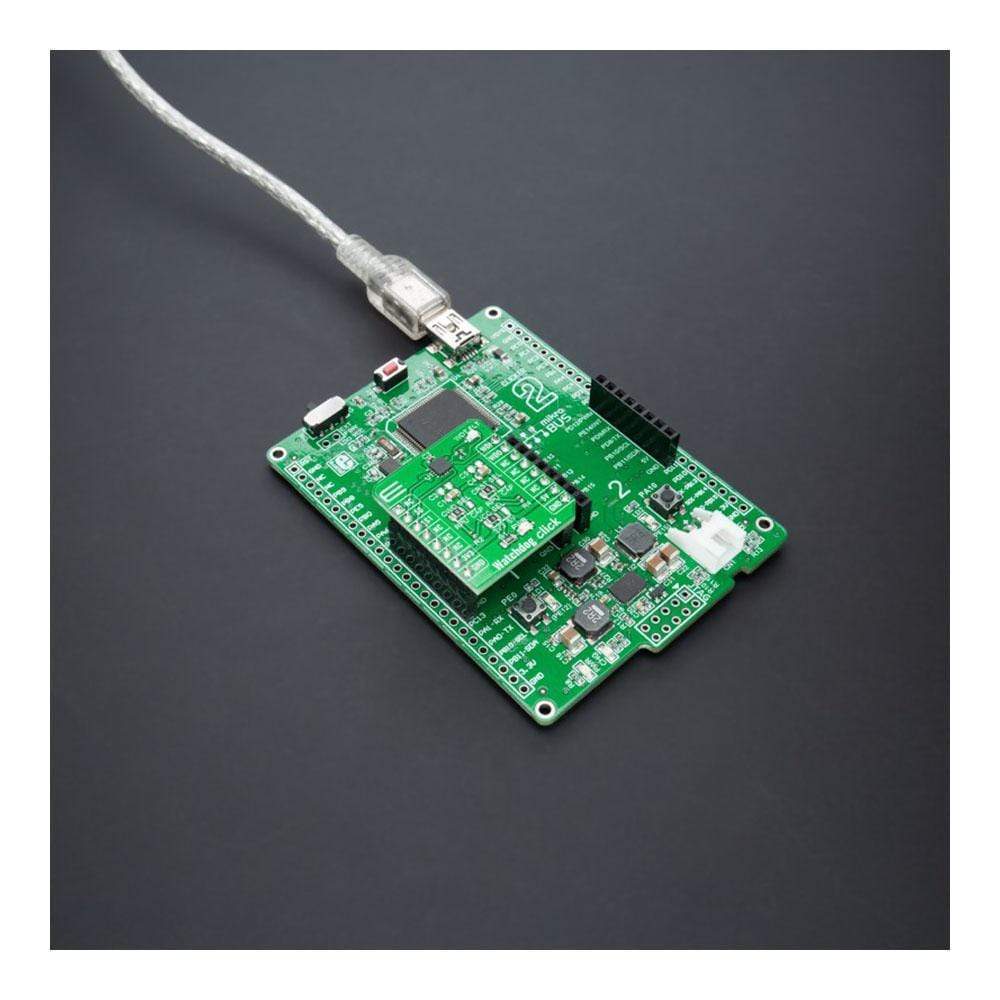
Le Watchdog Click Board™ est pris en charge par une bibliothèque compatible mikroSDK, qui comprend des fonctions qui simplifient le développement logiciel. Cette Click Board™ est un produit entièrement testé, prêt à être utilisé sur un système équipé du socket mikroBUS™.
How Does The Watchdog Click Board™ Work?
The Watchdog Click Board™ is based on the TPS3430, a standalone watchdog timer with a programmable watchdog window and resets delay from Texas Instruments. This high-accuracy programmable timer with the disable feature achieves 15% watchdog timing accuracy over the extended temperature range from –40°C to +125°C. A window watchdog is typically employed in safety-critical applications where a traditional watchdog timer is inadequate. With a traditional timer, there is a maximum time in which a pulse must be issued to prevent the reset from occurring. However, in a window watchdog, the pulse must be issued between a maximum lower window time and the minimum upper window time set by the programmable timeout pin and two logic input pins.
The Watchdog Click Board™ communicates with MCU using several GPIO pins and offers both programmable watchdog timeout and reset delay. The two pins that this Click board™ uses represent a watchdog input and output, with additional two logic inputs with which the user can select the watchdog window ratios, timeouts and disable the watchdog timer.
The watchdog input pin labeled as WDI routed on the PWM pin of the mikroBUS™ socket is ignored for the watchdog reset delay upon Start-Up. After Start-Up, the watchdog input signal must arrive within the watchdog window to prevent a watchdog reset whose delay duration may be configured with a CRST SEL on-board jumper. The user has two options, leaving the CRST pin pulled high with a pull-up resistor or connecting the CRST to a capacitor connected to GND. Similarly to the watchdog reset delay, the user can also configure the watchdog timeout using the S0 and S1 pins, routed on the RST and CS pins of the mikroBUS™ socket, and CWD SEL on-board jumper. This jumper can connect the CRST pin with a pull-up resistor or with a capacitor connected to GND.
When a watchdog fault occurs due to an incorrectly timed watchdog input signal, the WDO pin activates and performs the transition to logic low state for the period of the watchdog reset delay, which is also indicated with a red LED labelled as WDT FLT. When delay expires, the WDO pin deactivates and returns to a logic high state. When the watchdog is disabled using S0 and S1 pins, the watchdog input is ignored, and the WDO pin is in a Hi-Z and remains logic high due to the R5 external pull-up resistor.
The Watchdog Click Board™ is designed to operate with both 3.3V and 5V logic voltage levels selected via the VCC SEL jumper. It allows for both 3.3V and 5V capable MCUs to use the communication lines properly. However, the Click board™ comes equipped with a library that contains functions and an example code that can be used, as a reference, for further development.
SPECIFICATIONS
Type | RTC |
Applications | Can be used as a countdown timer in MCU, DSP, FPGA, ASIC, and many more. |
On-board modules | TPS3430 - standalone watchdog timer with a programmable watchdog window and reset delay from Texas Instruments |
Key Features | User-programmable watchdog window and reset delay, disable the feature, accuracy, high-precision, and more. |
Interface | GPIO |
Compatibility | mikroBUS |
Click board size | S (28.6 x 25.4 mm) |
Input Voltage | 3.3V or 5V |
PINOUT DIAGRAM
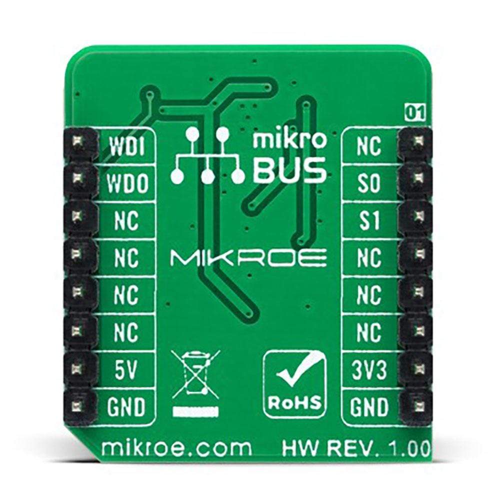
This table shows how the pinout on the Watchdog Click Board™ corresponds to the pinout on the mikroBUS™ socket (the latter shown in the two middle columns).
Notes | Pin | Pin | Notes | ||||
---|---|---|---|---|---|---|---|
NC | 1 | AN | PWM | 16 | WDI | Watchdog Input | |
Logic Set Pin 0 | S0 | 2 | RST | INT | 15 | WDO | Watchdog Output |
Logic Set Pin 1 | S1 | 3 | CS | RX | 14 | NC | |
NC | 4 | SCK | TX | 13 | NC | ||
NC | 5 | MISO | SCL | 12 | NC | ||
NC | 6 | MOSI | SDA | 11 | NC | ||
Power Supply | 3.3V | 7 | 3.3V | 5V | 10 | 5V | Power Supply |
Ground | GND | 8 | GND | GND | 9 | GND | Ground |
ONBOARD SETTINGS AND INDICATORS
Label | Name | Default | Description |
---|---|---|---|
LD1 | PWR | - | Power LED Indicator |
LD2 | WDO | - | WDT Reset LED Indicator |
JP2 | VCC SEL | Left | Logic Level Voltage Selection 3V3/5V: Left position 3V3, Right position 5V |
JP1 | CRST SEL | Left | WDT Reset Delay Selection RPU/CAP: Left position RPU, Right position CAP |
JP3 | CWD SEL | Left | WDT Timeout Selection RPU/CAP: Left position RPU, Right position CAP |
WATCHDOG CLICK ELECTRICAL SPECIFICATIONS
Description | Min | Typ | Max | Unit |
---|---|---|---|---|
Supply Voltage | 3.3 | - | 5 | V |
Maximum Output Current | - | - | 10 | mA |
Watchdog Reset Delay (RPU) | 8.5 | 10 | 11.5 | ms |
Operating Temperature Range | -40 | +25 | +125 | °C |
Software Support
We provide a library for the Watchdog Click Board™ on our LibStock page, as well as a demo application (example), developed using MikroElektronika compilers. The demo can run on all the main MikroElektronika development boards.
Library Description
The library covers all the necessary functions to control Watchdog Click board™.
Key Functions
void watchdog_send_pulse ( uint16_t p_duration_ms )
- Send pulse function.void watchdog_setup_time ( uint8_t setup_time_mode )
- Set the watchdog time function.void watchdog_reset_time ( void )
- Reset time function.
Example Description
The application is composed of three sections :
- System Initialization - Initializes GPIO, set RST, CS and PWM pin as outputs, set INT pin as input and begins to write log.
- Application Initialization - Initialization driver enables - GPIO, configure the watchdog window, enable watchdog and init. Timer Interrupt, also write log.
- Application Task - (code snippet) This is an example that demonstrates the use of the Watchdog Click board™. In the first part of the example, we send pulses in a valid time window (Correct Operation). The second part of the example sends pulses outside the valid time window and then the watchdog detects a fault condition, display "Fault", performs the reset and turn on the LED ( WDT FLT ) on the Watchdog Click board™. Results are being sent to the Usart Terminal where you can track their changes.
void application_task ( ) { watchdog_reset_time( ); watchdog_set_config( 50, 5 ); n_cnt = 100; while ( n_cnt > 0 ) { if ( watchdog_get_wdo( ) != 0 ) { mikrobus_logWrite( " Correct Operation ", _LOG_LINE ); Delay_ms( 1 ); n_cnt--; } } mikrobus_logWrite( "---------------------", _LOG_LINE ); watchdog_reset_time( ); watchdog_set_config( 120, 1 ); n_cnt = 50; while ( n_cnt > 0 ) { if ( watchdog_get_wdo( ) == 0 ) { mikrobus_logWrite( " Fault ", _LOG_LINE ); Delay_ms( 1 ); n_cnt--; } } mikrobus_logWrite( "---------------------", _LOG_LINE ); } The full application code, and ready to use projects can be found on our LibStock page.
Other mikroE Libraries used in the example:
- GPIO
- UART
Additional Notes and Information
Depending on the development board you are using, you may need a USB UART click, USB UART 2 click or RS232 click to connect to your PC, for development systems with no UART to USB interface available on the board. The terminal available in all MikroElektronika compilers, or any other terminal application of your choice, can be used to read the message.
MIKROSDK
The Watchdog Click Board™ is supported with mikroSDK - MikroElektronika Software Development Kit. To ensure proper operation of mikroSDK compliant Click board™ demo applications, mikroSDK should be downloaded from the LibStock and installed for the compiler you are using.
Frequently Asked Questions
Have a Question?
Be the first to ask a question about this.