Mikroelektronika d.o.o.
Planche à roulettes UT-M 7-Seg R Click
Impossible de charger la disponibilité du service de retrait


Overview
Le Click Board™ UT-M 7-Seg R est équipé de deux écrans LED 7-Seg ultra-minces CMS et du pilote LED à courant constant MAX6969 de Maxim Integrated. Le Click Board™ est conçu pour fonctionner sur une alimentation 3,3 V ou 5 V.
Il communique avec le microcontrôleur cible via l'interface SPI.
General Information | |
---|---|
Part Number (SKU) |
MIKROE-2746
|
Manufacturer |
|
Physical and Mechanical | |
Weight |
0.02 kg
|
Other | |
EAN |
8606018711345
|
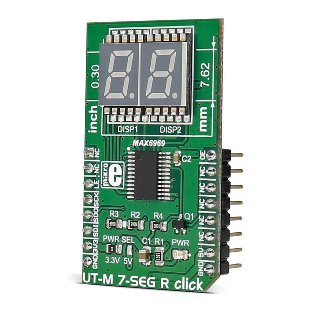
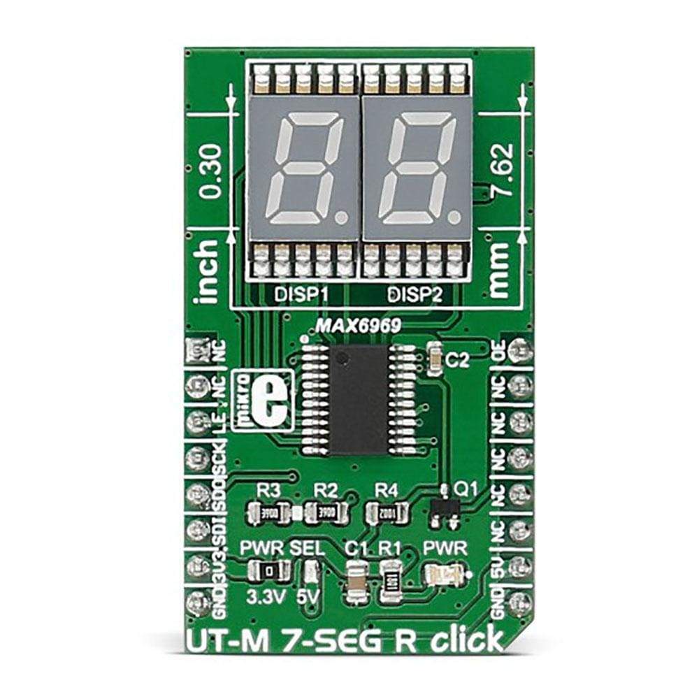
The UT-M 7-Seg R Click Board™ carries two SMD ultra thin LED 7-SEG displays and the MAX6969 constant-current LED driver from Maxim Integrated. The click is designed to run on either 3.3V or 5V power supply. 
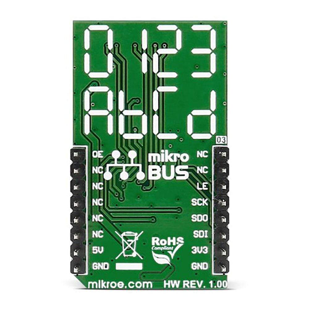
It communicates with the target microcontroller over SPI interface.
DISPLAY FEATURES
How Does The UT-M 7-Seg R Click Board™ Work?
The 7 segment displays are interfaced to the MCU over the MAX6969 16-port, constant-current LED driver IC.
It uses the common 4-wire serial bus for communication with the MCU itself (LE, SCK, SDO, SDI on mikroBUS™ pin socket).
There is an additional OE (output enable) pin which is used to control the output driver state (enabled/disabled). Since it is the PWM output pin on the mikroBUS™ by default, the LED segments light intensity could be controlled by software too.
MAX6969 DRIVER FEATURES
The MAX6969 uses the industry-standard, shift-register-plus-latch-type serial interface.
The driver accepts data shifted into a 16-bit shift register using data input DIN and clock input CLK. Input data appears at the DOUT output 16 clock cycles later to allow cascading of multiple MAX6969s . So, the IC allows you to connect multiple click boards™ - for applications that require more than two seven segment displays, such as digital clocks, temperature sensors, etc.
SPECIFICATIONS
Type | 7-segment,LED Segment |
Applications | Displaying digits and letters on two 7 segment displays |
On-board modules | MAX6969 6-Port, 5.5V Constant-Current LED Driver |
Key Features | Excellent character appearance, low power consumption |
Interface | SPI |
Compatibility | mikroBUS |
Click board size | M (42.9 x 25.4 mm) |
Input Voltage | 3.3V or 5V |
PINOUT DIAGRAM
This table shows how the pinout of the UT-M 7-Seg R Click Board™ corresponds to the pinout on the mikroBUS™ socket (the latter shown in the two middle columns).
Notes | Pin | ![]() |
Pin | Notes | |||
---|---|---|---|---|---|---|---|
NC | 1 | AN | PWM | 16 | OE | PWM control of light intensity | |
NC | 2 | RST | INT | 15 | NC | ||
Load-Enable input | LE | 3 | CS | TX | 14 | NC | |
Clock input | SCK | 4 | SCK | RX | 13 | NC | |
Serial Data Output | SDO | 5 | MISO | SCL | 12 | NC | |
Serial Data Input | SDI | 6 | MOSI | SDA | 11 | NC | |
Power supply | +3.3V | 7 | 3.3V | 5V | 10 | +5V | Power supply |
Ground | GND | 8 | GND | GND | 9 | GND | Ground |
JUMPERS AND SETTINGS
Designator | Name | Default Position | Default Option | Description |
---|---|---|---|---|
JP1 | PRW.SEL. | Left | 3V3 | Power Supply Voltage Selection 3V3/5V, left position 3V3, right position 5V |
Frequently Asked Questions
Have a Question?
Be the first to ask a question about this.