


Mikroelektronika d.o.o.
Planche à clic Stepper 8
Planche à clic Stepper 8
SKU: MIKROE-4157
Impossible de charger la disponibilité du service de retrait
Overview
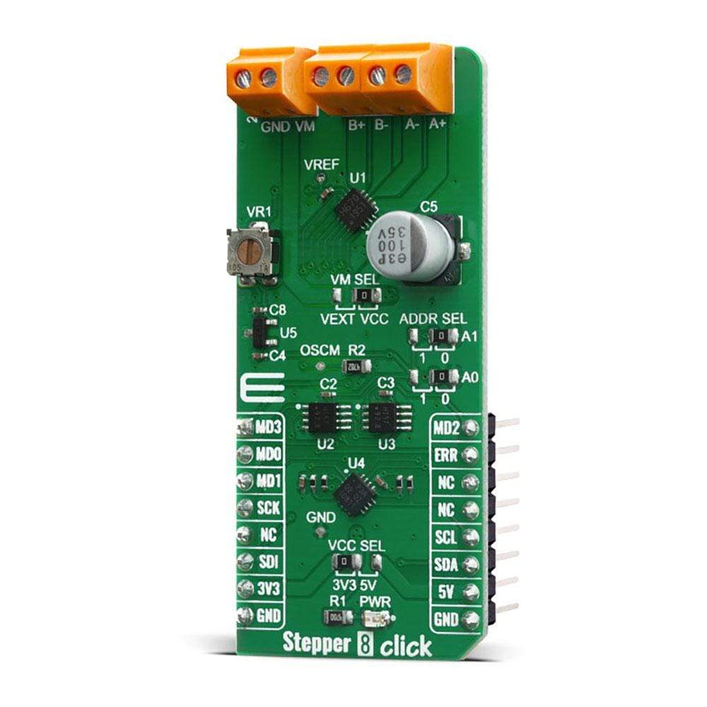
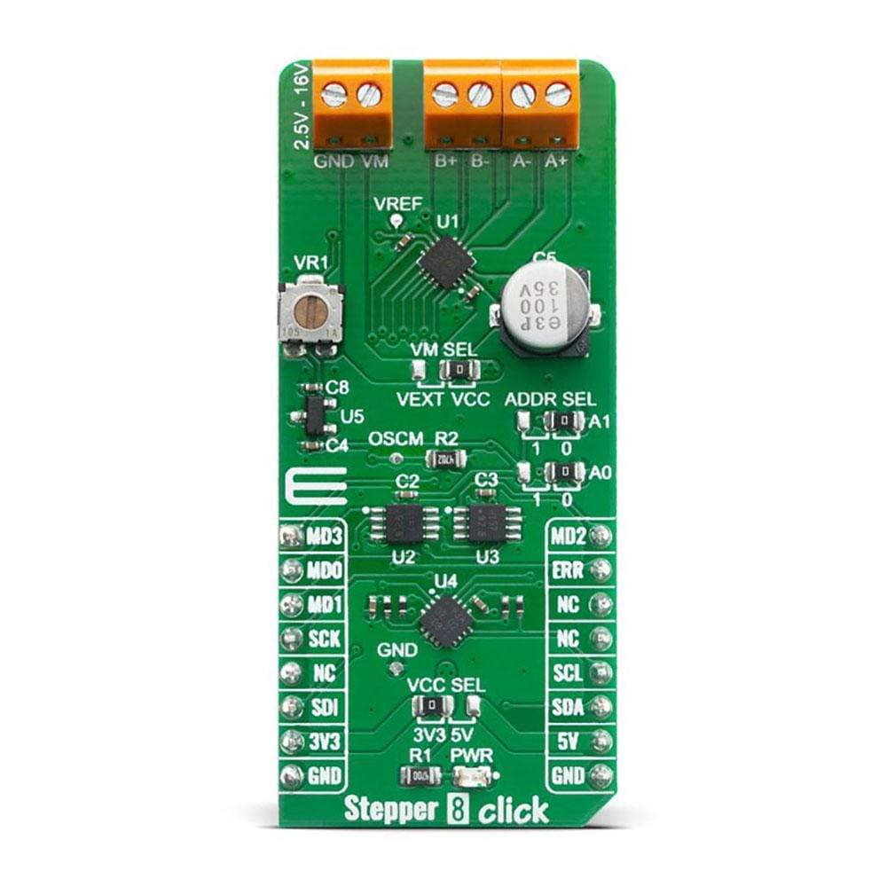
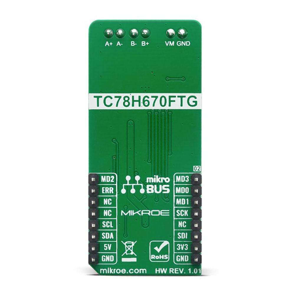
The Stepper 8 Click Board™ is a motor control add on board based on TC78H670FT from Toshiba. A clock-in and serial controlled Bipolar Stepping Motor Driver which can drive a 128 micro-stepping motor with a power supply ranging from 2.5V to 16V for a wide range of applications include USB-powered, battery-powered, and standard 9-12V system devices. A perfect solution for driving stepper motors in security cameras, portable printers, handheld scanners, pico-projectors, smartphones and many more.
Downloads
Le Stepper 8 Click Board™ est une carte de commande de moteur complémentaire basée sur le TC78H670FT de Toshiba. Un pilote de moteur pas à pas bipolaire à horloge et à commande série qui peut piloter un moteur à 128 micro-pas avec une alimentation allant de 2,5 V à 16 V pour une large gamme d'applications, notamment les appareils alimentés par USB, par batterie et les systèmes standard 9-12 V. Une solution parfaite pour piloter les moteurs pas à pas dans les caméras de sécurité, les imprimantes portables, les scanners portables, les pico-projecteurs, les smartphones et bien d'autres.
| General Information | |
|---|---|
Part Number (SKU) |
MIKROE-4157
|
Manufacturer |
|
| Physical and Mechanical | |
Weight |
0.022 kg
|
| Other | |
EAN |
8606018717606
|
Frequently Asked Questions
Have a Question?
Be the first to ask a question about this.