


Mikroelektronika d.o.o.
Planche à clic Stepper 5
Planche à clic Stepper 5
SKU: MIKROE-2624
Impossible de charger la disponibilité du service de retrait
Overview
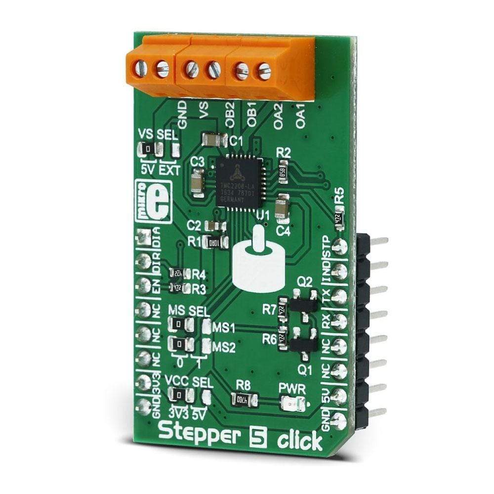
The Stepper 5 Click Board™ is the complete integrated bipolar step motor driver solution, rich with many features that allow silent operation and optimal working conditions for the connected motor.
The specialised TM2208 IC driver from Trinamic company far exceeds the capabilities of similar step motor drivers that are commonly used. In order to achieve such outstanding performances with a wide range of various step motors, this device features several technologies: stealth Chop2 - for silent motor operation; spreadCycle - highly dynamic, motor current control; microPlayer interpolation with 256 micro-steps.
Downloads
Le Stepper 5 Click Board™ est la solution complète de pilote de moteur pas à pas bipolaire intégré, riche de nombreuses fonctionnalités qui permettent un fonctionnement silencieux et des conditions de travail optimales pour le moteur connecté.
Le pilote de circuit intégré spécialisé TM2208 de la société Trinamic dépasse de loin les capacités des pilotes de moteur pas à pas similaires qui sont couramment utilisés. Afin d'obtenir des performances aussi exceptionnelles avec une large gamme de moteurs pas à pas différents, ce dispositif dispose de plusieurs technologies : stealth Chop2 - pour un fonctionnement silencieux du moteur ; spreadCycle - contrôle du courant du moteur hautement dynamique ; interpolation microPlayer avec 256 micro-pas.
| General Information | |
|---|---|
Part Number (SKU) |
MIKROE-2624
|
Manufacturer |
|
| Physical and Mechanical | |
Weight |
0.021 kg
|
| Other | |
EAN |
8606018713325
|
Frequently Asked Questions
Have a Question?
Be the first to ask a question about this.