


Mikroelektronika d.o.o.
Panneau de clic pour haut-parleur
Panneau de clic pour haut-parleur
Impossible de charger la disponibilité du service de retrait
Le Speaker Click Board™ est une carte complémentaire compacte qui contient un amplificateur de puissance audio avec une reproduction audio de haute qualité. Cette carte comprend le MAX9717, un amplificateur de puissance audio à architecture BTL (bridge-tied load) mono de 1,4 W de Maxim Integrated. Il fournit une puissance continue de 1,4 W dans une charge de 4 Ω à partir d'une seule alimentation +5 V, ou une puissance continue de 350 mW dans une charge de 8 Ω tout en fonctionnant à partir d'une seule alimentation +3,3 V. De plus, le MAX9717 dispose d'un amplificateur à gain réglable et d'une entrée de détection de casque qui détecte la connexion du casque à l'appareil, coupant le haut-parleur tout en pilotant le casque comme une charge asymétrique.
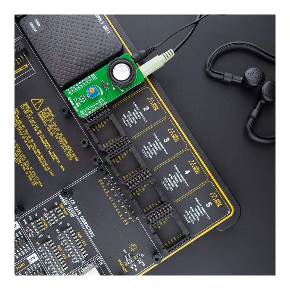
Le Speaker Click Board™ convient aux applications audio portables telles que les PDA et les appareils portables où l'espace et le coût sont d'une grande importance.
How Does The Speaker Click Board™ work?
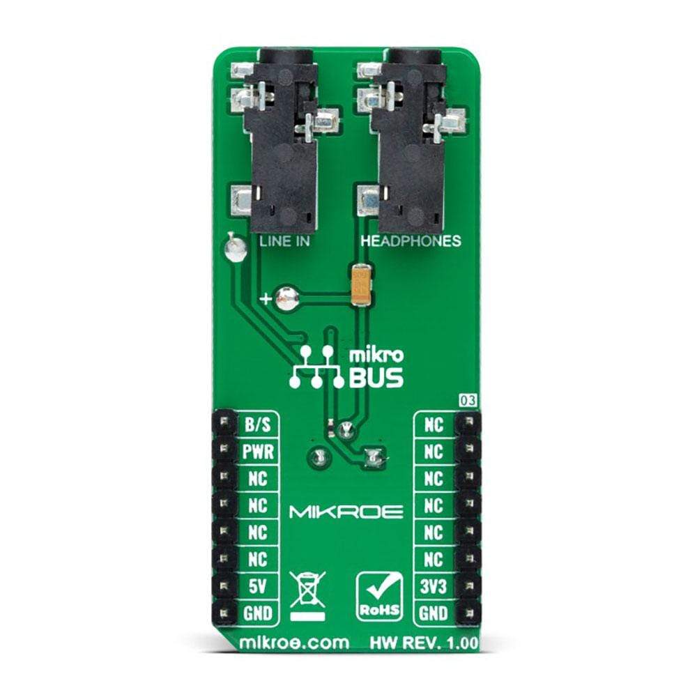
The Speaker Click Board™ as its foundation uses the MAX9717, a 1.4W mono bridge-tied load (BTL) architecture audio power amplifier with a high-quality audio reproduction from Maxim Integrated. It delivers 1.4W continuous power into a 4Ω load from a single +5V supply, or 350mW continuous power into an 8Ω load while operating from a single +3.3V supply. This device features Maxim's industry-leading, comprehensive click-and-pop suppression that reduces audible clicks and pops during Start-Up and Shutdown sequence. Output signal reproduction is possible through the onboard speaker, as well as through the headphone jack located on the bottom side of this Click board™.

The Speaker Click Board™ communicates with MCU using two GPIO pins routed on the PWM and INT pins of the mikroBUS™ socket labelled B/S and PWR. The MAX9717 features a low-power shutdown mode that reduces quiescent current consumption to 10nA. Entering shutdown mode is possible through the PWR pin, which disables the bias circuitry, and forces the amplifier outputs to GND through an internal 20kΩ resistor. Driving the PWR to a low logic state will cause MAX9717 to enter shutdown mode while the high state will perform a normal operation.
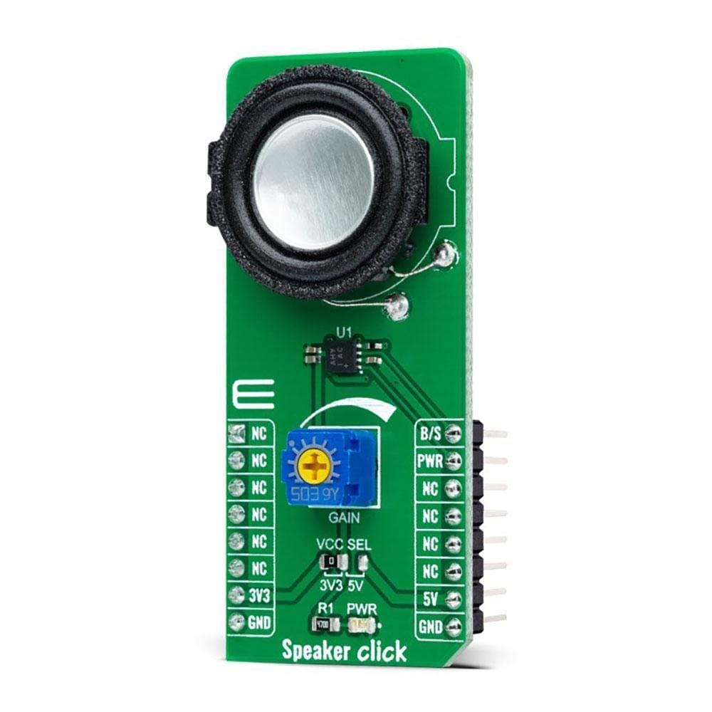
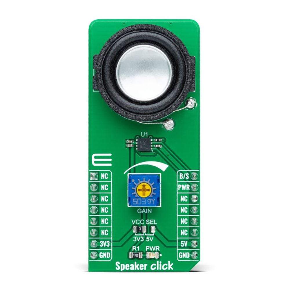
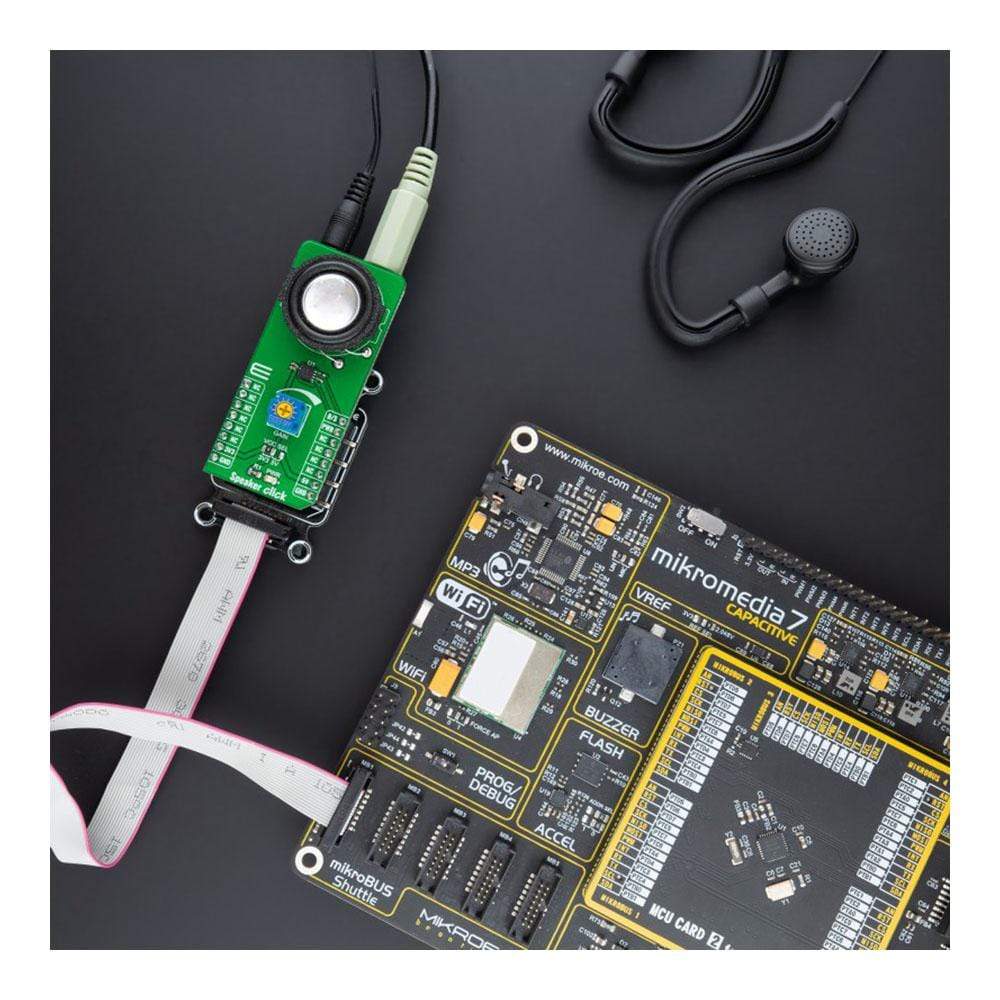
As mentioned before, this Click board™ has an onboard speaker, a 20mm 4Ω Premium Micro Transducer for sound reproduction. This speaker features a neodymium-iron-boron magnet, a light aluminium cone, and a high-temperature polycarbonate frame together with low resonant frequencies and a full-range bandwidth. Also, the MAX9717 features a headphone sense input pin, labelled as B/S, that senses headphone connection to the device through a 3.5mm jack connector labelled as HEADPHONES. This feature is muting the speaker while driving the headphone as a single-ended load. An adjustable potentiometer labelled as GAIN serves to adjust the gain of the MAXS9717's internal amplifier.
The Speaker Click Board™ can operate with both 3.3V and 5V logic voltage levels selected via the VCC SEL jumper. This way, it allows both 3.3V and 5V capable MCUs to use the GPIO lines properly. However, the Click board™ comes equipped with a library containing easy-to-use functions and an example code that can be used, as a reference, for further development.
SPECIFICATIONS
| Type | Speakers |
| Applications | Can be used for portable audio applications such as PDAs and portable devices where space and cost are of great importance. |
| On-board modules | MAX9717 - 1.4W mono bridge-tied load (BTL) architecture audio power amplifier with a high-quality audio reproduction from Maxim Integrated |
| Key Features | 1.4W mono audio amplifier, 10nA low-power Shutdown mode, no audible clicks or pops, adjustable gain option, headphone sense feature, and more. |
| Interface | GPIO |
| Compatibility | mikroBUS |
| Click board size | L (57.15 x 25.4 mm) |
| Input Voltage | 3.3V or 5V |
PINOUT DIAGRAM
This table shows how the pinout on the Speaker Click Board™ corresponds to the pinout on the mikroBUS™ socket (the latter shown in the two middle columns).
| Notes | Pin | Pin | Notes | ||||
|---|---|---|---|---|---|---|---|
| NC | 1 | AN | PWM | 16 | B/S | Headphone Sense | |
| NC | 2 | RST | INT | 15 | PWR | Shutdown | |
| NC | 3 | CS | RX | 14 | NC | ||
| NC | 4 | SCK | TX | 13 | NC | ||
| NC | 5 | MISO | SCL | 12 | NC | ||
| NC | 6 | MOSI | SDA | 11 | NC | ||
| Power Supply | 3.3V | 7 | 3.3V | 5V | 10 | 5V | Power Supply |
| Ground | GND | 8 | GND | GND | 9 | GND | Ground |
ONBOARD SETTINGS AND INDICATORS
| Label | Name | Default | Description |
|---|---|---|---|
| LD1 | PWR | - | Power LED Indicator |
| JP1 | VCC SEL | Left | Logic Level Voltage Selection 3V3/5V: Left position 3V3, Right position 5V |
| VR1 | GAIN | - | Gain Adjustment Potentiometer |
Software Support
We provide a library for the Speaker Click Board™ as well as a demo application (example), developed using MikroElektronika compilers. The demo can run on all the main MikroElektronika development boards.
The package can be downloaded/installed directly from NECTO Studio Package Manager(recommended way), downloaded from our LibStock™ or found on the mikroE Github account.
Library Description
This library contains API for Speaker Click driver.
Key Functions
speaker_cfg_setup- Config Object Initialization function.speaker_init- Initialization function.speaker_default_cfg- Click the Default Configuration function.
Example Description
This library contains an API for the Speaker click driver. This application controls the operating modes of the Speaker click board™.
The demo application is composed of two sections :
void application_task ( void ) {
 log_printf( &logger, "-------------------------rn" );
 log_printf( &logger, " Normal Operation Mode rn" );
 speaker_normal_operation( &speaker );
 Delay_ms( 10000 );
 log_printf( &logger, "-------------------------rn" );
 log_printf( &logger, " Enter Shutdown Mode rn" );
 speaker_shutdown( &speaker );
 Delay_ms( 10000 );
}
The full application code, and ready to use projects can be installed directly from NECTO Studio Package Manager(recommended way), downloaded from our LibStock™ or found on mikroE Github account.
Other mikroE Libraries used in the example:
- MikroSDK.Board
- MikroSDK.Log
- Click. Speaker
Additional Notes and Information
Depending on the development board you are using, you may need a USB UART click, USB UART 2 click or RS232 click to connect to your PC, for development systems with no UART to USB interface available on the board. The terminal available in all MikroElektronika compilers, or any other terminal application of your choice, can be used to read the message.
MIKROSDK
The Speaker Click Board™ is supported with mikroSDK - MikroElektronika Software Development Kit. To ensure proper operation of mikroSDK compliant Click board™ demo applications, mikroSDK should be downloaded from the LibStock and installed for the compiler you are using.
Panneau de clic pour haut-parleur
Frequently Asked Questions
Have a Question?
Be the first to ask a question about this.