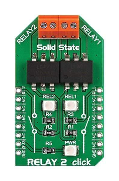
Carte relais 2 Click
Overview
La carte Relay 2 Click Board™ de MikroE est une carte complémentaire conçue pour les conceptions où l'utilisateur souhaite maintenir le microcontrôleur dans une relation marche/arrêt avec deux appareils différents en même temps, comme des lumières, des moteurs et d'autres appareils similaires.
La carte comprend deux relais statiques OptoMOS LCA717 qui assurent une commutation rapide, silencieuse et sans rebond. Elle dispose également de deux bornes à vis pour une connexion sécurisée. Avec une tension de blocage de 30 V, les deux relais ont un courant de charge élevé de 2 A et une résistance maximale à l'état passant très faible de 0,15'.
The Relay 2 Click Board™ is a dual relay click board™, equipped with two single-pole solid state relays (SSR), built with the patented OptoMOS® technology. These SSR devices allow reasonably high current, up to 2A and voltage up to 30V (peak-to-peak). These relays also allow very fast switching time, thanks to the absence of any moving parts inside of them. Compared to a mechanical relays, solid state relays offer a whole range of advantages, such as very high reliability, arc-free operation with no snubbing circuits required, great input/output galvanic isolation, no EM/RF interferences, low driving power needed, resistance to wear over time since they do not use any mechanical parts, and much more compact sizes, compared with the traditional mechanical relays.
Equipped with two SSRs, the Relay 2 Click Board™ is an ideal solution for power switching in both DC and AC applications. Due to its low power requirements, it can be controlled by the MCU pins, directly. It allows implementation of the MCU controlled power switching applications, such as the switches for the instrumentation and sensor circuitry power control, various I/O subsystems, control of various embedded electronic applications, and similar cases where reliable and clean power supply control is required.
Huw Does The Relay 2 Click Board™ Work?
The Relay 2 Click Board™ contains two LCA717 single poles OptoMOS® solid state relays (SSR), from IXYSIC. These SSRs are normally open, which means that there is no current flowing through the output terminals if no power is applied at the input - the output stage is in a state of an open circuit. The LCA717 itself is built with the patented OptoMOS® technology, that allows for a reasonably fast switching time to be achieved by the output stage. The input stage of the device is comprised of a highly efficient GaAIAs infrared LED, used to drive the photovoltaic elements of the SSR. The output stage has two N-type MOSFETs, which allow both DC and AC to be switched to the output stage. Input and output stage are galvanically isolated with up to 3.5kV of breakdown voltage.
The PWM and the AN pin of the mikroBUS™ are routed to the anodes of the integrated IR LEDs of each SSR, while the cathodes are connected to the GND. A positive voltage on these pins (in respect to the GND) will activate the first and the second SSR respectively. As already mentioned, the output MOSFETs are configured so that they can work with both AC and DC power sources. Therefore, the middle output of the LCA717 is not connected (NC). The input lines are also used to drive two LEDs labeled as REL1 and REL2, so the HIGH logic level on the PWM and AN pins will be indicated by these LEDs.
The Relay 2 Click Board™ contains two screw terminals so that the two external loads can be securely connected. Although the control of the Relay 2 Click Board™ is very easy and straightforward, there is a click library provided, which contains functions for even simpler control of the Relay 2 click. The included example demonstrates the usage of this click board™ and can be used as a reference for custom projects.
SPECIFICATIONS
Type | Relay |
Applications | It can be used as a MCU controlled switch for the instrumentation and sensor circuitry power control, various I/O subsystems, control of various embedded electronic applications, and similar cases where reliable and clean power supply control is required. |
On-board modules | Two LCA717 single-pole, OptoMOS® solid state relays |
Key Features | High reliability, arc-free operation with no snubbing circuits required, input/output galvanic isolation, no EM/RF interference, fast switching speed, no moving parts allow high endurance... |
Interface | GPIO |
Compatibility | mikroBUS |
Click board size | M (42.9 x 25.4 mm) |
Input Voltage | 3.3V |
PINOUT DIAGRAM
This table shows how the pinout of the Relay 2 Click Board™ corresponds to the pinout of the mikroBUS™ socket (the latter shown in the two middle columns).
Notes | Pin | Pin | Notes | ||||
---|---|---|---|---|---|---|---|
Relay 2 | RL2 | 1 | AN | PWM | 16 | RL1 | Relay 1 |
NC | 2 | RST | INT | 15 | NC | ||
NC | 3 | CS | RX | 14 | NC | ||
NC | 4 | SCK | TX | 13 | NC | ||
NC | 5 | MISO | SCL | 12 | NC | ||
NC | 6 | MOSI | SDA | 11 | NC | ||
Power supply | +3.3V | 7 | 3.3V | 5V | 10 | NC | |
Ground | GND | 8 | GND | GND | 9 | GND | Ground |
ONBOARD SETTINGS AND INDICATORS
Label | Name | Default | Description |
---|---|---|---|
LD1 | REL 1 | - | Relay 1 status LED, lights up when the SSR 1 is CLOSED |
LD2 | REL 2 | - | Relay 2 status LED, lights up when the SSR 2 is CLOSED |
LD3 | PWR | - | Power LED indicator |
Software Support
We provide a library for the Relay 2 Click Board™ on our Libstock page, as well as a demo application (example), developed using MikroElektronika compilers. The demo can run on all the main MikroElektronika development boards.
Library Description
The library offers an option to control the state of relays.
Key functions:
void relay_relay2Control( uint8_t pinState )
- Controls the Relay 2 pin.
void relay_relay1Control( uint8_t pinState )
- Controls the Relay 1 pin.
Example Description
The application is composed of three sections:
- System Initialization - Sets pin directions.
- Application Initialization - Initializes driver.
- Application Task - Turns relays on and off.
void applicationTask() { relay2_relay2Control( 1 ); relay2_relay1Control( 1 ); Delay_ms( 1000 ); relay2_relay2Control( 0 ); relay2_relay1Control( 0 ); Delay_ms( 1000 ); }
The full application code, and ready to use projects can be found on our Libstock page.
Other mikroE Libraries used in the example:
- UART
Additional Notes and Information
Depending on the development board you are using, you may need a USB UART click, USB UART 2 click or RS232 click to connect to your PC, for development systems with no UART to USB interface available on the board. The terminal available in all MikroElektronika compilers, or any other terminal application of your choice, can be used to read the message.
MIKROSDK
The Relay 2 Click Board™ is supported with mikroSDK - MikroElektronika Software Development Kit. To ensure proper operation of mikroSDK compliant click board demo applications, mikroSDK should be downloaded from the LibStock and installed for the compiler you are using.
Frequently Asked Questions
Have a Question?
Be the first to ask a question about this.